| View previous topic :: View next topic |
| Author |
Message |
autoguider
Joined: 24 Sep 2007
Posts: 82
Location: Aachen

|
 Posted: Sat Aug 15, 2020 1:10 pm Post subject: ATMega32 fusebits / MCSBootloader Posted: Sat Aug 15, 2020 1:10 pm Post subject: ATMega32 fusebits / MCSBootloader |
 |
|
Dear All,
in my 1st project with the ATMEGA32 I am in doubt on the settings of the fusebits as I cannot see how they are related to the information in the datasheet.
They are different to the 328p that I used in my other projects.
I am using a 6.144 MHz crystal with 2 capacitors 22pF for clock generation.
What is the correct Fusebit KLA987 setting ?
Is it 111111:Ext. Crystal/Resonator High Freq. ?
How does it correspond to the CK Sel Bits in the datasheet ?
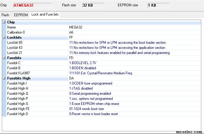
For flashing the MCS Bootloader I did selection as shown in For Bootloader.jpg
Are these settings correct for installing the bootloader?
[/img]
For the program that I want to upload via the MCS Bootloader.
What are the settings, esp. for the reset vector?
Please be so kind and advise.
kind regards
Christian
(BASCOM-AVR version : 2.0.8.3 ) |
|
| Back to top |
|
 |
EDC
Joined: 26 Mar 2014
Posts: 1135

|
| Posted: Sat Aug 15, 2020 6:33 pm Post subject: |
|
|
Ext crystal <8MHz, CKOPT Off, JTAG Disabled, Bootvector Enabled, Bootsize 1024 Words
It is also highly recommended to enable BODEN with choosen voltage.
 |
|
| Back to top |
|
|
autoguider
Joined: 24 Sep 2007
Posts: 82
Location: Aachen
|
| Posted: Sat Aug 15, 2020 8:27 pm Post subject: |
|
|
Thanks,
is this the setting for flashing the bootloader ?
Do I need different setting for flashing the application program via the bootloader? |
|
| Back to top |
|
|
MWS
Joined: 22 Aug 2009
Posts: 2335

|
| Posted: Sat Aug 15, 2020 9:20 pm Post subject: Re: ATMega32 fusebits / MCSBootloader |
|
|
| autoguider wrote: | | For flashing the MCS Bootloader I did selection as shown in For Bootloader.jpg |
The jpg is not consistent, as the value 99 for fuse high does not match fuse-bit high D = 0.
Fuse-bit high D is the BOOTRST fuse-bit.
Means as well you've set BOOTRST, you did not actually program the fuses.
If you would have done so, the fuse high would read 98.
BOOTRST = 0 is correct for jumping to the boot loader after reset.
A fuse bit is programmed if it reads 0.
| Quote: | | Do I need different setting for flashing the application program via the bootloader? |
With a boot loader used, the controller always jumps to the loader address first.
In case the loader hears its magic word, it invokes loader code, programs the flash, then either hard resets or invokes application code at &h0000.
If not, application code at &h0000 is executed after a timeout. |
|
| Back to top |
|
|
EDC
Joined: 26 Mar 2014
Posts: 1135
|
| Posted: Sun Aug 16, 2020 7:55 am Post subject: |
|
|
You can program Bootloader first, then FuseBits. You can program FuseBits and then Bootloader. Order don`t mather 
You can even open the Bootloader code then Right Click programmer icon and choose "Manual program" . On the FuseBits tab set correct setting and then hit "Write PRG" button.
This will add one line into the Bootloader code that instruct programmer to automatic write FuseBits during programming Bootloader code This is handy with more processor units.
Fuses are common for Bootloader and Application. So BOOTRST and BOOTSZ are specific for Boot but CLOCK setting are for Boot and App.
That means once programmed for Bootloader no need to change FuseBits for Application. |
|
| Back to top |
|
|
Duval JP
Joined: 22 Jun 2004
Posts: 1197
Location: France

|
| Posted: Mon Aug 17, 2020 11:20 am Post subject: |
|
|
it's always a little tricky to set the clock fuse.
the datasheet is difficult to translate for bad english people understanding like me
If a bascom user could explain the different options it would be a big plus.
for my part I always order 16MHz or 20Mhz quartz crystals with 2 caps of 18 or 15pf and I have'not datasheet about crystals
I'm never sure of my settings. I follow the Ben Zijlstra post about it
also in the setting page we have fusebit KLA987 but on the datasheet of M1284p i can't found any KLA fusebit ?
_________________
pleasure to learn, to teach, to create |
|
| Back to top |
|
|
autoguider
Joined: 24 Sep 2007
Posts: 82
Location: Aachen
|
| Posted: Thu Aug 20, 2020 9:29 am Post subject: |
|
|
To my opinion it is the ambiguity in the datasheets. I think quite often it is not clear what is meant by the term crystal oscillator.
Is it a device like this https://cdn-reichelt.de/documents/datenblatt/B400/OSZI.pdf or is it a quartz that needs the 2 capacitors ?
Then the naming in BASCOM is sometimes different from the naming in the datasheets.
E.g. BASCOM'S Fusebit KLA987 corresponds to SUT1,SUT0, CKSEL3..0 in the datasheet of the ATMEGA32.
Then the text in Bascom helps to identify. But it needs the effort to dig in several datasheets.
In the attachment I collected some data for the ATMEGA32 |
|
| Back to top |
|
|
Duval JP
Joined: 22 Jun 2004
Posts: 1197
Location: France
|
| Posted: Thu Aug 20, 2020 2:49 pm Post subject: |
|
|
Thanks Christian,
I will post an new sugject about Crystal

_________________
pleasure to learn, to teach, to create |
|
| Back to top |
|
|
albertsm
Joined: 09 Apr 2004
Posts: 6197
Location: Holland
|
| Posted: Thu Aug 20, 2020 3:16 pm Post subject: |
|
|
| Quote: | | crystal oscillator. |
this is a circuit consisting on an oscillator, the actual crystal, and the optional capacitors. one of them could be a variable capacitor.
the oscillator electronics circuit is usually build into the processor. and the crystal you add.
you can also add a ceramic resonator.
and there exist complete oscillator circuits that need vcc and gnd and output a frequency. then there are temperature controlled oscillator circuits. etc/
but you are right, often i have to take a good look in the datasheet too, to see what the mean.
it is nice of somebody explains all the differences. also the stability and power consumption.
in bascom you find names like KLM etc.
The reason is simple : AVR started with AT90S2313. Atmel had no names for fuses as there were no fuses. So when fuses were added to AVR, there were no default names.
A simple letter was used to indicate a fuse. but these letters are of non importance. only the value is. In fact these letters should not even been shown.
For xmega and xtiny you find another fuse system and also a description closer to atmel/microchip description.
_________________
Mark |
|
| Back to top |
|
|
|


