| View previous topic :: View next topic |
| Author |
Message |
murmel
Joined: 13 Oct 2014
Posts: 20

|
 Posted: Fri Jan 05, 2024 5:56 pm Post subject: Adafruit MAX31865 is not sending data Posted: Fri Jan 05, 2024 5:56 pm Post subject: Adafruit MAX31865 is not sending data |
 |
|
Hi,
I need urgent help.
It's about the Adafruit module MAX31865 with a PT1000.
Connected it is like this.
MEGA32 ---> Adafruit module MAX31865
GND ---> GND
+5V ---> +5V
MOSI ---> MOSI
MISO ---> MISO
SCK ---> SCK
CS(PB2) ---> CS
I modified a program from H.Kipnik.
Here is the link to the data sheet of the MAX31865.
https://www.analog.com/media/en/technical-documentation/data-sheets/max31865.pdf
Unfortunately I don't get any data from the MAX31865.
After calculation the display is -256.
The jumper on the module are set for 2 wires.
Who can help?
The initialization is probably wrong, but I'm too stupid for that.
Here is the program.
| Code: | '**************************************************************************************************
'
' Programmteile von H.Kipnik
'
'**************************************************************************************************
$regfile = "m32def.dat" ' CPU
$crystal = 16000000 ' Frequenz
$baud = 19200 ' use baud rate
$hwstack = 80 ' HW stack
$swstack = 80 ' SW stack
$framesize = 80 ' Frame space
Config Lcd = 20x4
Config Lcdpin = Pin , Db4 = Porta.4 , Db5 = Porta.5 , Db6 = Porta.6 , Db7 = Porta.7 , E = Portc.6 , Rs = Portc.7
Config Lcdbus = 4
Cursor Off : Cls
Config Portb.1 = Output ' Backlight LCD
Portb.0 = 1
Waitms 500
Config Spi = Hard , Interrupt = Off , Data_order = Msb , Master = Yes , Polarity = High , Phase = 1 , Clockrate = 16 , Noss = 1
Spiinit
Dim Max_32865_config_register As Byte ' configregister
Dim Rtd As Integer
Dim Rtd_l As Byte At Rtd Overlay
Dim Rtd_h As Byte At Rtd Overlay + 1
Dim Temperatur As Single
Max_32865_config_register = &B11100011
Config Portb.2 = Output
Max_cs Alias Portb.2
Max_cs = 1
Max_cs = 0
Spiout Max_32865_config_register , 1
Max_cs = 1
'***************** Mainloop *********************
Do
Max_cs = 0
Spiin Rtd_h , 1
Spiin Rtd_l , 1
Max_cs = 1
Temperatur = Rtd / 32
Temperatur = Temperatur - 256
Locate 1 , 1
Lcd "MSB: " ; Rtd_h
Locate 2 , 1
Lcd "LSB: " ; Rtd_l
Locate 3 , 1
Lcd "Temperatur :" ; Temperatur
Waitms 500
Loop
|
If I have forgotten any information, please ask. Thanks again for your help.
Regards,
Murmel
(BASCOM-AVR version : 2.0.8.6 ) |
|
| Back to top |
|
 |
MWS
Joined: 22 Aug 2009
Posts: 2335

|
| Posted: Fri Jan 05, 2024 7:36 pm Post subject: |
|
|
As you do not care about the SS-pin, it is likely the controller is not in Master-SPI mode.
doesn't do that, it only tells the hard-SPI interface not to control the SS-pin, thus it's your task to control it.
See the datasheet, to hold the SPI in Master-mode (the only mode implemented in Bascom) you either have to:
- set SS (PB4) to output
- set SS to input and pull high, can be done by internal pullup |
|
| Back to top |
|
|
murmel
Joined: 13 Oct 2014
Posts: 20
|
| Posted: Sat Jan 06, 2024 4:57 pm Post subject: |
|
|
Hello MWS,
I made NOSS=0 and connected pin SS(PB4) to the CS of the module. The module is still not responding. There is still a small error in the program. The module is equipped with a MAX31865, the program says MAX32865. Another addition, it's this module:
https://www.adafruit.com/product/3328
What else can I do?
Greetings
Murmel |
|
| Back to top |
|
|
programmista123
Joined: 31 Jan 2018
Posts: 191

|
| Posted: Sat Jan 06, 2024 7:33 pm Post subject: |
|
|
Hi,
I can see that you don't have anywhere address byte.
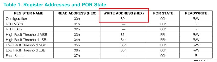
For example: Spiout Max_32865_config_register - you are sending configuration only but to which address? (should be &H80)
The same situation for read - you need to write address byte before reading data (datasheet, page 5th).
Regards,
Przemek |
|
| Back to top |
|
|
murmel
Joined: 13 Oct 2014
Posts: 20
|
| Posted: Sat Jan 06, 2024 8:17 pm Post subject: |
|
|
Hello Przemek,
I've been looking for examples for days but can't find anything. If you could help I would be very grateful. Attention, this is the MAX31865!
I'll post the correct file again.
| Code: |
'**************************************************************************************************
'
' Programmcode z.T. von H.Kipnik https://www.roboternetz.de/community/archive/index.php/t-75139.html
'
' https://www.analog.com/media/en/technical-documentation/data-sheets/max31865.pdf
'
'
'**************************************************************************************************
$regfile = "m32def.dat" ' CPU
$crystal = 16000000 ' Frequenz
$baud = 19200 ' use baud rate
$hwstack = 80 ' HW stack
$swstack = 80 ' SW stack
$framesize = 80 ' Frame space
Config Lcd = 20x4
Config Lcdpin = Pin , Db4 = Porta.4 , Db5 = Porta.5 , Db6 = Porta.6 , Db7 = Porta.7 , E = Portc.6 , Rs = Portc.7
Config Lcdbus = 4
Cursor Off : Cls
Config Portb.1 = Output ' Backlight LCD
Portb.0 = 1
Waitms 500
Config Spi = Hard , Interrupt = Off , Data_order = Msb , Master = Yes , Polarity = High , Phase = 1 , Clockrate = 16 , Noss = 1
Spiinit
Dim Max_31865_config_register As Byte ' config register
Dim Rtd As Integer
Dim Rtd_l As Byte At Rtd Overlay
Dim Rtd_h As Byte At Rtd Overlay + 1
Dim Temperatur As Single
Max_31865_config_register = &B11100011
Config Portb.2 = Output
Max_cs Alias Portb.2
Max_cs = 1
Max_cs = 0
Spiout Max_31865_config_register , 1
Max_cs = 1
'***************** Mainloop *********************
Do
Max_cs = 0
Spiin Rtd_h , 1
Spiin Rtd_l , 1
Max_cs = 1
Temperatur = Rtd / 32
Temperatur = Temperatur - 256
Locate 1 , 1
Lcd "Rtd_h: " ; Rtd_h
Locate 2 , 1
Lcd "Rtd_l: " ; Rtd_l
Locate 3 , 1
Lcd "RTD : " ; Rtd
Locate 4 , 1
Lcd "Temperatur :" ; Temperatur
Waitms 500
Loop |
Where and how do I have to insert the addressing of the registers?
Thanks
Greetings
Murmel |
|
| Back to top |
|
|
MWS
Joined: 22 Aug 2009
Posts: 2335
|
| Posted: Sat Jan 06, 2024 9:58 pm Post subject: |
|
|
| murmel wrote: | | What else can I do? |
I suggest to double-check your connections, as well the data-sheet use the SDI/SDO nomenclature, thus:
MOSI ATM32 --> SDI MAX31865
MISO ATM32 --> SDO MAX31865
| Quote: | | the program says MAX32865 |
There's no device from Maxim named MAX32865, it can be an edit error or an author's mnemonic.
Why do you not link the source of your code?
If one follows up this link from Sat Jan 06, 2024 8:17 pm, MAX31855 via SPI ansprechen:
https://www.roboternetz.de/community/archive/index.php/t-75139.html
The 31855 is a different device than the 31865.
Again your follow-up code shows NOSS=1 and again you must set PB4 to output then or pull it high. Is this understood?
Looks like you have to program fresh from the start according the data sheet or you can try to understand/translate the arduino library at github for this device.
Allover it looks like a pretty chaotic approach. |
|
| Back to top |
|
|
EDC
Joined: 26 Mar 2014
Posts: 1135
|
| Posted: Sat Jan 06, 2024 10:29 pm Post subject: |
|
|
Maybe you can adapt some code from MAX31856?
https://www.mcselec.com/index2.php?option=com_forum&Itemid=59&page=viewtopic&t=14653&highlight=max31856
| Code: | $regfile = "m328pdef.dat"
$crystal = 16000000
$hwstack = 64
$swstack = 32
$framesize = 128
$baud = 115200
Config Submode = New
$projecttime = 239
'MAX31856 od -210 °C do 1800 °C step 0,0078125 °C.
Const Spi_mode = 0 '0=Shiftin/Shiftout 1=Hardware SPI, 2=Software SPI ,
Const Region = 1 'for some code folding
#if Region
Const Max31856_cr0_reg = &H00 ' Config 0 register
Const Max31856_cr0_autoconvert = &H80 ' Config 0 Auto convert flag
Const Max31856_cr0_1shot = &H40 ' Config 0 one shot convert flag
Const Max31856_cr0_ocfault1 = &H20 ' Config 0 open circuit fault 1 flag
Const Max31856_cr0_ocfault0 = &H10 ' Config 0 open circuit fault 0 flag
Const Max31856_cr0_cj = &H08 ' Config 0 cold junction disable flag
Const Max31856_cr0_fault = &H04 ' Config 0 fault mode flag
Const Max31856_cr0_faultclr = &H02 ' Config 0 fault clear flag
Const Max31856_cr1_reg = &H01 ' Config 1 register
Const Max31856_mask_reg = &H02 ' Fault Mask register
Const Max31856_cjhf_reg = &H03 ' Cold junction High temp fault register
Const Max31856_cjlf_reg = &H04 ' Cold junction Low temp fault register
Const Max31856_lthfth_reg = &H05 ' Linearized Temperature High Fault Threshold Register, MSB
Const Max31856_lthftl_reg = &H06 ' Linearized Temperature High Fault Threshold Register, LSB
Const Max31856_ltlfth_reg = &H07 ' Linearized Temperature Low Fault Threshold Register, MSB
Const Max31856_ltlftl_reg = &H08 ' Linearized Temperature Low Fault Threshold Register, LSB
Const Max31856_cjto_reg = &H09 ' Cold-Junction Temperature Offset Register
Const Max31856_cjth_reg = &H0A ' Cold-Junction Temperature Register, MSB
Const Max31856_cjtl_reg = &H0B ' Cold-Junction Temperature Register, LSB
Const Max31856_ltcbh_reg = &H0C ' Linearized TC Temperature, Byte 2
Const Max31856_ltcbm_reg = &H0D ' Linearized TC Temperature, Byte 1
Const Max31856_ltcbl_reg = &H0E ' Linearized TC Temperature, Byte 0
Const Max31856_sr_reg = &H0F ' Fault Status Register
Const Max31856_fault_cjrange = &H80 ' Fault status Cold Junction Out-of-Range flag
Const Max31856_fault_tcrange = &H40 ' Fault status Thermocouple Out-of-Range flag
Const Max31856_fault_cjhigh = &H20 ' Fault status Cold-Junction High Fault flag
Const Max31856_fault_cjlow = &H10 ' Fault status Cold-Junction Low Fault flag
Const Max31856_fault_tchigh = &H08 ' Fault status Thermocouple Temperature High Fault flag
Const Max31856_fault_tclow = &H04 ' Fault status Thermocouple Temperature Low Fault flag
Const Max31856_fault_ovuv = &H02 ' Fault status Overvoltage or Undervoltage Input Fault flag
Const Max31856_fault_open = &H01 ' Fault status Thermocouple Open-Circuit Fault flag
Const Max31856_tctype_b = &B0000_0000
Const Max31856_tctype_e = &B0000_0001
Const Max31856_tctype_j = &B0000_0010
Const Max31856_tctype_k = &B0000_0011
Const Max31856_tctype_n = &B0000_0100
Const Max31856_tctype_r = &B0000_0101
Const Max31856_tctype_s = &B0000_0110
Const Max31856_tctype_t = &B0000_0111
Const Max31856_vmode_g8 = &B0000_1000
Const Max31856_vmode_g32 = &B0000_1100
#endif
'####################### SPI CONFIGURATIONS #######################
'-[BELOW VALID FOR ARDUINO NANO HARDWARE SPI]-
'ARDUINO NANO
' D13-SCK PB5
' D12-MISO PB4
' D11-MOSI PB3
' D10-SS PB2
#if Spi_mode = 0 ' SHIFTOUT/SHIFTIN
Spi_ss Alias Portb.2 : Config Spi_ss = Output : Set Spi_ss
Sck Alias Portb.5 : Config Sck = Output 'Output Clock
Di_pin Alias Pinb.4 : Config Di_pin = Input : Set Portb.4 'Input Pullup DataIn
Do_pin Alias Portb.3 : Config Do_pin = Output 'Output DataOut
#elseif Spi_mode = 1 ' HARDWARE SPI '
Spi_ss Alias Portb.2 : Config Spi_ss = Output : Set Spi_ss 'for SPI MASTER SS must be Output
Portb.3 = 1 'pull up on miso
'4 minimum, 16, 64, 128 next
Config Spi = Hard , Interrupt = Off , Data_order = Msb , Master = Yes , Polarity = High , Phase = 1 , Clockrate = 128 , Noss = 1 , Spiin = 255
Spiinit
#elseif Spi_mode = 2 'SOFTWARE SPI
Spi_ss Alias Portb.2 : Config Spi_ss = Output : Set Spi_ss
Config Spi = Soft , Din = Pinb.4 , Dout = Portb.3 , Ss = None , Clock = Portb.5
Spiinit
#endif
Dim Spibuff(4) As Byte
Dim Rbyte As Byte At Spibuff(1) Overlay
Dim Rword As Word At Spibuff(1) Overlay
Dim Rlong As Long
Sub Write_reg(byval Reg_addr As Byte , Byval Reg_val As Byte)
Set Reg_addr.7 'for write
#if Spi_mode 'mode 1 & 2 (HARD & SOFT)
Reset Spi_ss
Spiout Reg_addr , 1
Spiout Reg_val , 1
Set Spi_ss
#else 'mode 0 (SHIFTOUT/SHIFTIN)
Reset Spi_ss
Shiftout Do_pin , Sck , Reg_addr , 0
Shiftout Do_pin , Sck , Reg_val , 0
Set Spi_ss
#endif
End Sub
Sub Read_regs(byval Reg_addr As Byte , Byval Bytes As Byte)
#if Spi_mode 'mode 1 & 2 (HARD & SOFT)
Reset Spi_ss
Spiout Reg_addr , 1
Spiin Spibuff(1) , Bytes
Set Spi_ss
Select Case Bytes
Case 2 : Swap Rword
Case 3
Rlong = Spibuff(1)
Shift Rlong , Left , 8
Rlong = Rlong + Spibuff(2)
Shift Rlong , Left , 8
Rlong = Rlong + Spibuff(3)
End Select
#else 'mode 0 (SHIFTOUT/SHIFTIN)
Reset Spi_ss
Shiftout Do_pin , Sck , Reg_addr , 0
Select Case Bytes
Case 1 : Shiftin Di_pin , Sck , Rbyte , 0
Case 2 : Shiftin Di_pin , Sck , Rword , 0
Case 3 : Shiftin Di_pin , Sck , Spibuff(1) , 0 , 24
Rlong = Spibuff(1)
Shift Rlong , Left , 8
Rlong = Rlong + Spibuff(2)
Shift Rlong , Left , 8
Rlong = Rlong + Spibuff(3)
End Select
Set Spi_ss
#endif
End Sub
Sub Set_thermocouple_type(byval Ttype As Byte)
Call Read_regs(max31856_cr1_reg , 1)
Rbyte = Rbyte And &B1111_0000 'clearing 4 bottom bits
Rbyte = Rbyte Or Ttype 'setting 4 bottom bits
Call Write_reg(max31856_cr1_reg , Rbyte)
End Sub
Sub Set_50hz_noise_filter() ' default filter is 60Hz
Call Read_regs(max31856_cr0_reg , 1)
Set Rbyte.0
Call Write_reg(max31856_cr0_reg , Rbyte)
End Sub
Sub One_shot_temperature()
Call Write_reg(max31856_cjto_reg , &H00)
Call Read_regs(max31856_cr0_reg , 1)
Rbyte.7 = 0 'reset bit 7 (turn off autoconvert)
Rbyte = Rbyte Or Max31856_cr0_1shot 'set bit 6 (one shot conversion)
Call Write_reg(max31856_cr0_reg , Rbyte)
End Sub
Sub Read_fault()
Call Read_regs(max31856_sr_reg , 1)
End Sub
Function Read_cjt_temp() As String
Local Temps As Single
Call One_shot_temperature() : Waitms 250
Call Read_regs(max31856_cjth_reg , 2) 'read back a WORD
Temps = Rword
Temps = Temps / 256.0
Read_cjt_temp = Fusing(temps , "#.&&")
End Function
Function Read_thermocouple_temp()as String
Local Temps As Single
Call One_shot_temperature() : Waitms 250
Call Read_regs(max31856_ltcbh_reg , 3)
If Rlong.23 = 1 Then Rlong.31 = 1 'remember sign
Shift Rlong , Right , 5 , Signed 'not used 5 bottom bits
Temps = Rlong * 0.0078125
Read_thermocouple_temp = Fusing(temps , "#.&&")
End Function
Function Decode_error() As String
Select Case Rbyte
Case &B1000_0000
Decode_error = "Cold Junction Range Fault"
Case &B0100_0000
Decode_error = "Thermocouple Range Fault"
Case &B0010_0000
Decode_error = "Cold Junction High Fault"
Case &B0001_0000
Decode_error = "Cold Junction Low Fault"
Case &B0000_1000
Decode_error = "Thermocouple High Fault"
Case &B0000_0100
Decode_error = "Thermocouple Low Fault"
Case &B0000_0010
Decode_error = "Over/Under Voltage Fault"
Case &B0000_0001
Decode_error = "Thermocouple Open Fault"
End Select
End Function
Call Write_reg(max31856_mask_reg , &H00)
Call Write_reg(max31856_cr0_reg , Max31856_cr0_ocfault0)
Call Set_thermocouple_type(max31856_tctype_k)
Call Set_50hz_noise_filter()
Do
Print "Cold Junction Temp: " ; Read_cjt_temp()
Print "Thermocouple Temp: " ; Read_thermocouple_temp()
Call Read_fault()
If Rbyte <> 0 Then Print Decode_error()
Wait 1
Loop
End |
_________________
Check B-Flash -my MCS bootloader app for Android (updated) |
|
| Back to top |
|
|
murmel
Joined: 13 Oct 2014
Posts: 20
|
| Posted: Sun Jan 07, 2024 7:47 pm Post subject: |
|
|
@MWS: the name MAX32865 was a typo and should only be corrected. The source of the code is in the head of the program! I tried to get ideas from it.
I can't translate the Arduino library.
@EDC: Great work!!! I'll try to get some ideas from this.
Thank you for your answers.
Greetings Murmel |
|
| Back to top |
|
|
EDC
Joined: 26 Mar 2014
Posts: 1135
|
|
| Back to top |
|
|
murmel
Joined: 13 Oct 2014
Posts: 20
|
| Posted: Thu Jan 11, 2024 7:58 pm Post subject: |
|
|
Hello EDC,
thanks for the example code. Unfortunately it only reads the LSB part (LSB and MSB are the same).
Maybe you will find an error.
Here the code:
| Code: |
'**************************************************************************************************
'
' Programmcode z.T. von H.Kipnik https://www.roboternetz.de/community/archive/index.php/t-75139.html
'
' https://www.analog.com/media/en/technical-documentation/data-sheets/max31865.pdf
'
'**************************************************************************************************
$regfile = "m32def.dat" ' CPU
$crystal = 16000000 ' Frequenz
$baud = 19200 ' use baud rate
$hwstack = 80 ' HW stack
$swstack = 80 ' SW stack
$framesize = 80 ' Frame space
Config Lcd = 20x4
Config Lcdpin = Pin , Db4 = Porta.4 , Db5 = Porta.5 , Db6 = Porta.6 , Db7 = Porta.7 , E = Portc.6 , Rs = Portc.7
Config Lcdbus = 4
Cursor Off : Cls
Config Portb.1 = Output ' Backlight LCD
Portb.0 = 1
Waitms 500
Config Spi = Hard , Interrupt = Off , Data_order = Msb , Master = Yes , Polarity = High , Phase = 1 , Clockrate = 128 , Noss = 1
Spiinit
Dim Rtd As Integer
Dim Rtd_h As Byte At Rtd Overlay
Dim Rtd_l As Byte At Rtd Overlay + 1
Dim Temperatur As Single
Dim Write_address As Byte
Dim Read_address_1 As Byte
Dim Read_address_2 As Byte
Dim Max_31865_config_register As Byte ' config register
Write_address = &B10000000 ' Config writeaddress
Read_address_1 = &B00000001 ' RTD_h Read Address
Read_address_2 = &B00000010 ' RTD_l Read Address
Max_31865_config_register = &B11100011 ' MAX-Konfiguration
Config Portb.2 = Output
Max_cs Alias Portb.2
Max_cs = 1
Max_cs = 0
Spiout Write_address , 1 ' Configregister beschreiben
Spiout Max_31865_config_register , 1
Max_cs = 1
'***************** Mainloop *********************
Do
Max_cs = 0 ' read Highbyte MSB
Spiout Read_address_1 , 1
Spiin Rtd_h , 1
Max_cs = 1
Max_cs = 0 ' read Lowbyte LSB
Spiout Read_address_2 , 1
Spiin Rtd_l , 1
Max_cs = 1
Temperatur = Rtd / 32
Temperatur = Temperatur - 256
Locate 1 , 8
Lcd " "
Locate 2 , 8
Lcd " "
Locate 3 , 8
Lcd " "
Locate 4 , 6
Lcd " "
Locate 1 , 1
Lcd "RTD_h: " ; Rtd_h
Locate 2 , 1
Lcd "RTD_l: " ; Rtd_l
Locate 3 , 1
Lcd "RTD : " ; Rtd
Locate 4 , 1
Lcd "Temp: " ; Temperatur
Waitms 500
Loop |
Greetings Murmel |
|
| Back to top |
|
|
programmista123
Joined: 31 Jan 2018
Posts: 191
|
| Posted: Thu Jan 11, 2024 8:37 pm Post subject: |
|
|
Hi,
Try use EDC's code from the end of the post - it should read both registers (MSB and LSB).
Regards,
Przemek |
|
| Back to top |
|
|
EDC
Joined: 26 Mar 2014
Posts: 1135
|
|
| Back to top |
|
|
murmel
Joined: 13 Oct 2014
Posts: 20
|
| Posted: Mon Jan 15, 2024 6:40 pm Post subject: |
|
|
Hello programmista123, Hello EDC
@programmista123 I tried the code, it has the same result, LSB and MSB are the same.
| Code: | Max_cs = 0
Spiout Read_address_1 , 1
Spiin Rtd_h , 1
Spiin Rtd_l , 1
Max_cs = 1 |
@EDC Your suggestion only brings zeros  Here is the code Here is the code
| Code: | '**************************************************************************************************
'
' Programmcode z.T. von H.Kipnik https://www.roboternetz.de/community/archive/index.php/t-75139.html
'
' https://www.analog.com/media/en/technical-documentation/data-sheets/max31865.pdf
'
'
'**************************************************************************************************
$regfile = "m32def.dat" ' CPU
$crystal = 16000000 ' Frequenz
$baud = 19200 ' use baud rate
$hwstack = 80 ' HW stack
$swstack = 80 ' SW stack
$framesize = 80 ' Frame space
Config Lcd = 20x4
Config Lcdpin = Pin , Db4 = Porta.4 , Db5 = Porta.5 , Db6 = Porta.6 , Db7 = Porta.7 , E = Portc.6 , Rs = Portc.7
Config Lcdbus = 4
Cursor Off : Cls
Config Portb.1 = Output ' Backlight LCD
Portb.0 = 1
Waitms 500
Config Spi = Hard , Interrupt = Off , Data_order = Msb , Master = Yes , Polarity = High , Phase = 1 , Clockrate = 128 , Noss = 1
Spiinit
Dim Rtd As Integer
Dim Rtd_h As Byte At Rtd Overlay
Dim Rtd_l As Byte At Rtd Overlay + 1
Dim Temperatur As Single
Dim Write_address As Byte
Dim Read_address_1 As Byte
Dim Read_address_2 As Byte
Dim Max_31865_config_register As Byte ' config register
Write_address = &B10000000 ' Config writeaddress
Read_address_1 = &B00000001 ' RTD_h Read Address
Read_address_2 = &B00000010 ' RTD_l Read Address
Max_31865_config_register = &B11100011 ' MAX-Konfiguration
Config Portb.2 = Output
Max_cs Alias Portb.2
Max_cs = 1
Max_cs = 0
Spiout Write_address , 1 ' Configregister beschreiben
Spiout Max_31865_config_register , 1
Max_cs = 1
'***************** Mainloop *********************
Do
'( Max_cs = 0 ' read Highbyte MSB
Spiout Read_address_1 , 1
Spiin Rtd_h , 1
Max_cs = 1
Max_cs = 0 ' read Lowbyte LSB
Spiout Read_address_2 , 1
Spiin Rtd_l , 1
Max_cs = 1
Max_cs = 0
Spiout Read_address_1 , 1
Spiin Rtd_h , 1
Spiin Rtd_l , 1
Max_cs = 1
')
Dim Myrtd As Word
Dim Mybuff (2) As Byte At Myrtd Overlay
Dim Myfault As Byte
Reset Max_cs
Spiout Read_address_1 , 1
Spiin Mybuff (1) , 2
Set Max_cs
Temperatur = Myrtd / 32
Temperatur = Temperatur - 256
Locate 1 , 8
Lcd " "
Locate 2 , 8
Lcd " "
Locate 3 , 8
Lcd " "
Locate 4 , 6
Lcd " "
Locate 1 , 1
Lcd "RTD_h: " ; Rtd_h
Locate 2 , 1
Lcd "RTD_l: " ; Rtd_l
Locate 3 , 1
Lcd "RTD : " ; Rtd
Locate 4 , 1
Lcd "Temp: " ; Temperatur
Waitms 500
Loop |
I'm at the end. Do you have another idea?
greetings murmel |
|
| Back to top |
|
|
EDC
Joined: 26 Mar 2014
Posts: 1135
|
|
| Back to top |
|
|
programmista123
Joined: 31 Jan 2018
Posts: 191
|
| Posted: Mon Jan 15, 2024 7:03 pm Post subject: |
|
|
Hi,
Maybe in this case we should take one step back and check what you're reading from sensor after PoR?
Regards,
Przemek |
|
| Back to top |
|
|
|
|
You cannot post new topics in this forum
You cannot reply to topics in this forum
You cannot edit your posts in this forum
You cannot delete your posts in this forum
You cannot vote in polls in this forum
You cannot attach files in this forum
You cannot download files in this forum
|
|