| View previous topic :: View next topic |
| Author |
Message |
sentinel
Joined: 02 Feb 2009
Posts: 141
Location: Tasmania

|
 Posted: Sat Jan 22, 2022 1:43 am Post subject: Posted: Sat Jan 22, 2022 1:43 am Post subject: |
 |
|
Thank you for the schematic, O-Family. There are many similarities to mine.
I think that the answer is, as you said, to leave out the BOD. It seems to be causing an unwanted reset on power up in my circuit and I'm not sure that it's worth having. Without it, the power cycling behaviour is fine.
I'll continue to think about this issue and about ways to improve the recovery from Powersave. |
|
| Back to top |
|
 |
sentinel
Joined: 02 Feb 2009
Posts: 141
Location: Tasmania
|
| Posted: Sat Jan 22, 2022 4:01 am Post subject: |
|
|
EDC - the program flow as I see it is this.
Start: Initialise and enable Watchdog
Main loop: Reset WD every loop.
If power goes off, disable WD to save power
When power returns, re-enable WD
Continue resetting WD every loop.
If chip hangs for whatever reason, the WD isr is called and program flow is directed to address 0000
The instructions Enable Wdt and Start Watchdog are executed again before the main program loop.
By resetting the WD many times per second in the main loop only, it ensures that the program is flowing correctly. If the WD reset was in the sectic isr, the program could be stuck in some infinite loop in the main loop but the WD would never overflow to save the day. |
|
| Back to top |
|
|
MWS
Joined: 22 Aug 2009
Posts: 2262

|
| Posted: Sat Jan 22, 2022 12:22 pm Post subject: |
|
|
| O-Family wrote: | | BOD is not used. |
There's quite a difference between a hobby project clock and a commercial product like it seems to be the case here.
In the first it doesn't matter if EEProm gets corrupted, or the controller's running nuts because of an under-voltage issue.
For the second such is completely unacceptable, thus BOD is required.
I have explained already: the supercap's charging resistor is the culprit, as any power drawn by the controller creates a voltage drop via the charging resistor, and that in turn triggers BOD.
Conclusion:
1) There's no issue while the controller is in sleep, as a few micro-amps do not create noticeable voltage drop.
2) It is a lesser issue, if the controller just awakes from sleep and executes _sectic, but then the drop is already about 0.2 Volt, which limits full use of the supercap's charge a bit.
3) It is a big issue, if the controller wakes up completely but too early, while PSU's voltage is still rising. Any power the controller sources itself to output pins will create a bigger voltage drop via the charging resistor, leading to BOD-reset.
The time while this may occur is very short, exactly the time between around 1V and full rise of Vbat, but it may be long enough to trigger BOD.
3) can be improved with a delay as suggested, which makes the controller doing its full job only as PSU's voltage is fully up.
2) and maybe 3) already can be improved by an low leakage capacitor parallel to Vbat/GND. A Schottky diode parallel to the supercap's charging resistor would additionally bypass the resistor, allowing for higher current drawn from the supercap without voltage dropping too much. A Schottky with minimal forward voltage is desirable. |
|
| Back to top |
|
|
sentinel
Joined: 02 Feb 2009
Posts: 141
Location: Tasmania
|
| Posted: Sun Jan 23, 2022 2:13 am Post subject: |
|
|
That makes sense. Your suggestion of the Schottky diode is good and I'm adding it to the redesign that I'm finishing now.
I suspect that part of the problem is the choice of voltage sensing point. If, instead, a point upstream of the 3V3 regulator is chosen, suitably divided and clamped to the 3V3 rail, this would provide an earlier signal which would make Powersave happen while the mains supply is still dropping but still holding up the 3V3 rail.
Combined with your delay suggestion I expect a better result with BOD enabled.
[img]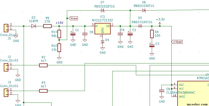 [/img] [/img] |
|
| Back to top |
|
|
O-Family
Joined: 23 May 2010
Posts: 320
Location: Japan

|
| Posted: Sun Jan 23, 2022 2:56 am Post subject: |
|
|
I do not recommend stopping BOD.
Not all products have BOD enabled.
I ship many products with my hobby works.
If you need backup with supercapacitors, BOD consumes a lot of power and needs to be stopped.
If his circuit design is such that supercapacitors are frequently emptied, it is better to use batteries such as lithium ion.
You have the choice of adopting BOD safety measures or ensuring backup time with supercapacitors.
Backing up with supercapacitors is meaningless if the design is such that BOD occurs frequently.
If it is important to protect the EEPROM from corruption due to an AVR runaway near 1.7V, you can either review the backup circuit to enable BOD, or choose to duplicate the EEPROM or protect the data with a checksum. |
|
| Back to top |
|
|
sentinel
Joined: 02 Feb 2009
Posts: 141
Location: Tasmania
|
| Posted: Sun Jan 23, 2022 5:50 am Post subject: |
|
|
My intention is to have BOD enabled in future. There have been some instances of EEPROM corruption in the past and micro-controller freezing which is a huge hassle as the devices are not readily accessible. There is no way to reset a microcontroller that you cannot access other than by disconnecting power and waiting for the supercapacitor to discharge over many hours. It is dangerous to re-apply power too early, because then the supercapacitor is recharged and you have to restart the waiting period, so you have to err on the long side.
By using the Picopower version, we can disable the BOD during Powersave to reduce current consumption, then re-enable it when power is restored.
The reliability of the product is more important than the duration of the battery back-up, and if necessary, the size of the supercapacitor can easily be increased (currently 0.22F). |
|
| Back to top |
|
|
Paulvk
Joined: 28 Jul 2006
Posts: 1257
Location: SYDNEY
|
| Posted: Sun Jan 23, 2022 7:18 am Post subject: |
|
|
| sentinel wrote: |
The reliability of the product is more important than the duration of the battery back-up, and if necessary, the size of the supercapacitor can easily be increased (currently 0.22F). |
So why not use a primary lithium cell instead of a capacitor you might get 7 to 10 years before it needs replacement. |
|
| Back to top |
|
|
O-Family
Joined: 23 May 2010
Posts: 320
Location: Japan
|
| Posted: Sun Jan 23, 2022 8:36 am Post subject: |
|
|
If you disable BOD during power save, I think you can't prevent the AVR from running out of control and damaging the EEPROM when the power supply is around 1.7V.
The built-in power-on reset of the AVR works, and the AVR may run unstable.
If reliability is important, it is a good idea to install a low power consumption reset IC externally.
Since the transient phenomenon of power supply rise and fall is also affected by changes due to the environment such as temperature, the problem may reoccur even if it is temporarily escaped by the program Wait. |
|
| Back to top |
|
|
MWS
Joined: 22 Aug 2009
Posts: 2262
|
| Posted: Sun Jan 23, 2022 3:19 pm Post subject: |
|
|
| sentinel wrote: | | Schottky diode is good and I'm adding it to the redesign that I'm finishing now. |
My idea is to put the Schottky parallel to charging resistor R8 the direction if charged from IC1, R8 still serves as protection/charging resistor.
As soon supply via IC1 shuts down, the Schottky bridges R8 and allows for less voltage drop if higher currents are drawn from C3.
| Quote: | | I suspect that part of the problem is the choice of voltage sensing point. |
Agreed.
| Quote: | | If, instead, a point upstream of the 3V3 regulator is chosen, suitably divided and clamped to the 3V3 rail, this would provide an earlier signal which would make Powersave happen while the mains supply is still dropping but still holding up the 3V3 rail. |
As you clamp it to VO of IC1, I fear it won't work as supposed.
Imho actual supply voltage VO coming from IC1 has to be the target.
Be aware in active mode VCC of M168 is about 0,22V lower than VO of IC1 because of Vf of D5, equals about 3.1V.
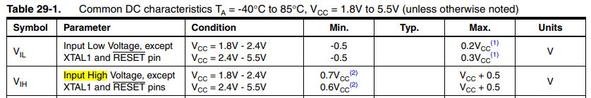
Looked up again pin's threshold voltages, do not remember where I got that 1 Volt from, however in 7530KAVR07/14, page 277 it is given for VCC at 3.1V with:
High: 1.6V
Low: 1.5V
With some tolerances - see the datasheet yourself.
I would not use a voltage divider, subtracting a voltage would give a sharper result, which would help to counter tolerances.
What do you think about: IC1/VO --- 1N4148 --- Power_on pin --- pulldown 15k ---GND ?
This would result in:
power-good: >= 2.3V
power-fail: <= 2.2V
At the very moment the controller wakes up by power-good, the real voltage at VCC is 0.22V lower, but already higher than BOD voltage of 1.8V.
A delay may be needless then. |
|
| Back to top |
|
|
sentinel
Joined: 02 Feb 2009
Posts: 141
Location: Tasmania
|
| Posted: Mon Jan 24, 2022 1:14 am Post subject: |
|
|
Paulvk - Partly through stubbornness, partly because I want to improve devices that have already been made and partly because the board might sit on a shelf for months before being installed.
O-family - I agree that the BOD is necessary for reliability. I originally believed that the BOD only protected spurious EEPROM writes when values were being written at very low voltages, but it seems that faulty operation can happen at other times too.
I would prefer to keep the reset function in the micro partly because the WD isr can save the current date and time which, although it could end up being a few seconds or minutes out, is still better than starting the clock at midight on Jan 1st 1970.
MWS - that looks like a neat solution, but the thresholds that I saw in the datasheet were, Low - 1V (0.3 x 3V3) and High - 2V (0.6 x 3V3).

IC1-VO = 3.54V (measured) when Vcc is 3.3V, giving the Vf of the Schottky as 0.24V
Assuming a Vf of the 1N4148 of 0.7V, then Vpower_on will always be 0.46V below Vcc, so for a low Vpower_on threshold value of 1V, Vcc will have already dropped to 1.46V
In other words, Vcc would drop below the BOD of 1V8 before the Power_on sense line reached 1V.
Two 1N4148 diodes in series might do the job. |
|
| Back to top |
|
|
sentinel
Joined: 02 Feb 2009
Posts: 141
Location: Tasmania
|
| Posted: Mon Jan 24, 2022 2:10 am Post subject: |
|
|
To me, the great advantage of having the Vpower_on sense line come from a 5:1 voltage divider at the input to the 3.3V regulator is that there is early warning of a power cut, allowing the micro to go into Powersave without draining the supercapacitor of any charge. This is because the input to the voltage regulator is still at 5V when the 1V low threshold is reached, telling the micro to go into Powersave.
At 5V input to the regulator, the micro is still being supplied with 3.3V mains power.
When power returns, the supply to the regulator will have already reached 10V when the signal to come out of Powersave (2V on the Power_on input) is triggered.
So, under all conditions, the system is well behaved, being able to shut down early and start up late. |
|
| Back to top |
|
|
MWS
Joined: 22 Aug 2009
Posts: 2262
|
| Posted: Mon Jan 24, 2022 8:23 pm Post subject: |
|
|
| sentinel wrote: | | MWS - that looks like a neat solution, but the thresholds that I saw in the datasheet were, Low - 1V (0.3 x 3V3) and High - 2V (0.6 x 3V3). |
Can't agree on that one, check the diagram, datasheet is version 9365AAVR02/16.
| Quote: | | To me, the great advantage of having the Vpower_on sense line come from a 5:1 voltage divider at the input to the 3.3V regulator is that there is early warning of a power cut, allowing the micro to go into Powersave without draining the supercapacitor of any charge. This is because the input to the voltage regulator is still at 5V when the 1V low threshold is reached, telling the micro to go into Powersave. |
If this is your intention, then your schema from 'Sun Jan 23, 2022 2:13 am' is wrong. As you clamp to IC1/VO the higher voltage will prevail, and this is VO and not the weak output from the divider. |
|
| Back to top |
|
|
sentinel
Joined: 02 Feb 2009
Posts: 141
Location: Tasmania
|
| Posted: Tue Jan 25, 2022 5:57 am Post subject: |
|
|
So many variants! So many datasheets!
But OK, even with those thresholds, I still say that it performs well.
| Quote: | | As you clamp to IC1/VO the higher voltage will prevail, and this is VO and not the weak output from the divider. |
Since the Schottky clamps the sense line to the regulator output, the sense line can never go higher than 0.2V (the Schottky Vf) above the 3.3V regulator output, so technically, the lower voltage wil prevail.
I've done a simulation of the voltages with rising and falling supply levels and you can see that whenever the sense voltage is below the pin change thresholds (rising or falling), the regulator has the full 3.3V output.
[img]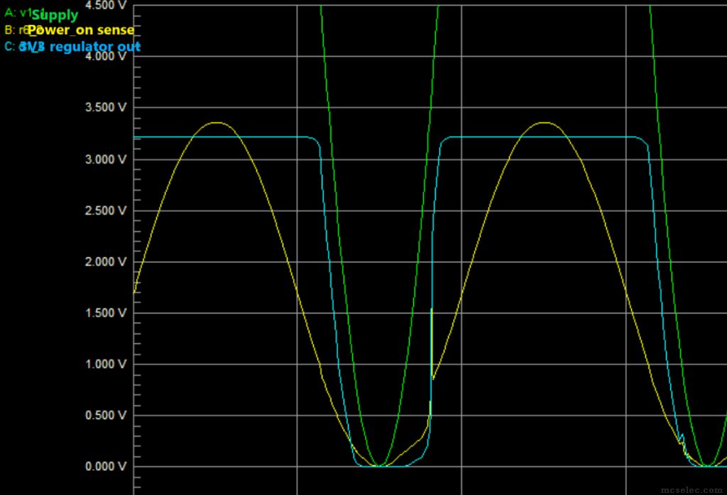 [/img] [/img] |
|
| Back to top |
|
|
MWS
Joined: 22 Aug 2009
Posts: 2262
|
| Posted: Tue Jan 25, 2022 1:26 pm Post subject: |
|
|
| sentinel wrote: | | But OK, even with those thresholds, I still say that it performs well. |
Your desire I see well, but to disagree I have to. 
| Quote: | | Since the Schottky clamps the sense line to the regulator output, the sense line can never go higher than 0.2V (the Schottky Vf) above the 3.3V regulator output |
The sense line is pretty weak with these resistor values, it will be overridden.
| Quote: | | so technically, the lower voltage wil prevail. |
No.
| Quote: | | I've done a simulation of the voltages with rising and falling supply levels |
Me too.
| Quote: | | and you can see that whenever the sense voltage is below the pin change thresholds (rising or falling), the regulator has the full 3.3V output. |
Your interpretation of your simulation result is wrong.
Check my simulation, white is power_good, green is Vbat to M168.
Vbat is always lower than power_good, results in power good is signaled to early and power no-good too late. |
|
| Back to top |
|
|
sentinel
Joined: 02 Feb 2009
Posts: 141
Location: Tasmania
|
| Posted: Tue Jan 25, 2022 3:20 pm Post subject: |
|
|
My apologies, I might not have been clear that the point in the circuit that connects to the micro-controller Power_on sense pin is the junction of R10 and R14 in my schematic (perhaps confusingly labelled Vraw). It's the junctiom of R2 & R3 in yours.
Your D1 (my D?) Schottky is just there to stop that Vraw voltage from exceeding the maximum permitted port input voltage.
We may have been talking at cross purposes. |
|
| Back to top |
|
|
|
|
You cannot post new topics in this forum
You cannot reply to topics in this forum
You cannot edit your posts in this forum
You cannot delete your posts in this forum
You cannot vote in polls in this forum
You cannot attach files in this forum
You cannot download files in this forum
|
|


