| View previous topic :: View next topic |
| Author |
Message |
Davide
Joined: 25 Sep 2005
Posts: 93

|
 Posted: Sun Dec 05, 2021 1:25 pm Post subject: Posted: Sun Dec 05, 2021 1:25 pm Post subject: |
 |
|
Hello MWS,
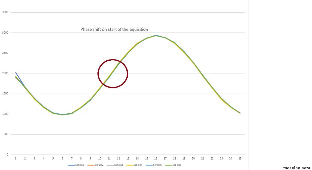
Thanks for the great tip! Despite a marginal correction Tcd0_cnt=0 your code improved a lot the result, almost the 6 trails overlap, have a look at the picture:
| Quote: | | How about a few times oversampling climbing-algo with alternating acquisition of two channels? |
What do you mean with the above advice? Sampling both channel in scan to have almost a simultaneous sampling one sample apart each other?
Davide |
|
| Back to top |
|
 |
MWS
Joined: 22 Aug 2009
Posts: 2335

|
| Posted: Sun Dec 05, 2021 3:53 pm Post subject: |
|
|
| Davide wrote: | | What do you mean with the above advice? |
You know what a climbing algorithm is?
Start accounting as soon the current sampled value is higher than the previous, stop accounting if it becomes lower.
This gives a representation of the ascending edge of the sinus. Can also be done with the descending edge and filtering can be applied to compensate for distortions.
Calculate the middle of the edge and you have the zero crossing, do this 5 or 10 times (oversampling) and use the mean value.
Sample 2 channels simultaneously - which should be an option of the xmegas - and use above oversampling.
The distance between zero-crossings is known then as reverse of frequency and the zero-crossing difference between two channels, included the slight delay between sampled channels, gives the phase shift.
This would make the AC useless, which imho is a weakness by design, if it comes to real-world conditions, unclean sinus a.s.o.
If I'd be wrong, if the AC works well for the application also under critical conditions, why not use the AC for both sinus inputs and calculate the difference?
Should be possible to measure lengths of 5 periods of sinus A (ICP is the key), use a timer to create a timestamp, calculate the mean period, add period to timestamp to start measuring sinus B in phase of sinus A.
Sample 5 times sinus B with AC, have the timestamp timer running, calculate mean of difference = phase shift. |
|
| Back to top |
|
|
Davide
Joined: 25 Sep 2005
Posts: 93
|
| Posted: Sun Dec 05, 2021 9:50 pm Post subject: |
|
|
Hi MWS,
Honestly I am quite intrigue to try the double ADC channel, sampling the ADC CH0 and CH1 without the AC trigger and then compare their samples, if I understood correctly the ADC in sweep mode will collect samples with a deterministic delay of 1 sample between two channels.
I will give it a try, first I have to realize how to use DMA with two ADC channels, perhaps two channels DMA, one each ADC channel. |
|
| Back to top |
|
|
JC
Joined: 15 Dec 2007
Posts: 628
Location: Cleveland, OH

|
| Posted: Mon Dec 06, 2021 4:03 am Post subject: |
|
|
It might not matter to you, but you might want to check on the Xmega's DMA operations.
On high end chips the DMA runs simultaneously with the processor's main core ( s ).
Its been a while since I read the Xmega DMA documents, and no, I didn't check this evening, but IIRC they do not run in the background, they actually stall the main core.
For your data acquisition phase, that may not matter.
(The Event System, however, does run simultaneously with the micro's core.)
JC |
|
| Back to top |
|
|
Davide
Joined: 25 Sep 2005
Posts: 93
|
| Posted: Sat Dec 11, 2021 9:49 am Post subject: |
|
|
Hello,
recently I am trying to acquire both signal via DMA with the ADC in sweep mode but I can't find the way, when I select the free run mode I receive the both channels correctly but if I select single ADC mode and sweep on the second ADC channel only 0 are received.
I will post some code when I reach something sharable, I have the same issue without the DMA so it looks the problem belongs to the setting of the ADC, I will try more in the weekend.
D. |
|
| Back to top |
|
|
MWS
Joined: 22 Aug 2009
Posts: 2335
|
| Posted: Sat Dec 11, 2021 10:13 am Post subject: |
|
|
| Davide wrote: | | recently I am trying to acquire both signal via DMA with the ADC in sweep mode but I can't find the way, when I select the free run mode I receive the both channels correctly |
This is then the hard work.
http://ww1.microchip.com/downloads/en/Appnotes/00002535A.pdf
| Quote: | | so it looks the problem belongs to the setting of the ADC |
Also my opinion.
AN2535 tells it should work:
| Quote: | 3.2 Event System
To improve conversion timing and further offload work from the CPU, the ADC is connected to the XMEGA Event System. This makes it possible to use incoming events to trigger single conversions or conversion sweeps across several channels. |
|
|
| Back to top |
|
|
Davide
Joined: 25 Sep 2005
Posts: 93
|
| Posted: Sat Dec 11, 2021 10:53 am Post subject: |
|
|
The section forward to event system AN --> http://ww1.microchip.com/downloads/en/appnotes/doc8071.pdf
4.2 Sweep of 4 ADC Channels on Timer/Counter Overflow
The ADC can be configured to do a sweep of four channels on any event. In this
example, a Timer/Counter overflow event is used. This can be very useful when the
Timer/Counter is used for PWM generation, as the ADC sampling can be
synchronized to the PWM.
4.2.1 Configuration
This example shows how to configure a sweep of the four virtual channels of ADCA
on an overflow of TCC0, using event channel 0.
1. Configure TCC0 with the desired frequency and period.
2. Select the TCC0 overflow event as an event source for event channel 0.
3. Configure ADCA for a four-channel sweep.
4. Configure ADCA to start sweep on event, using event channel 0. |
|
| Back to top |
|
|
Davide
Joined: 25 Sep 2005
Posts: 93
|
| Posted: Sat Dec 11, 2021 11:42 am Post subject: |
|
|
I will give a try of example 2 from that AN
void Example2( void )
{
/* Select TC overflow as event channel 0 multiplexer input. */
EVSYS_SetEventSource( 0, EVSYS_CHMUX_TCC0_OVF_gc );
/* Configure ADC A event channel and configure which channels to sweep
* and enable channel sweep.
*/
ADCA.EVCTRL = (uint8_t) ADC_SWEEP_0123_gc | ADC_EVSEL_0123_gc | ADC_EVACT_SWEEP_gc;
/* Configure the input of the ADC cannels and single ended mode. */
ADCA.CH0.MUXCTRL = (uint8_t) ADC_CH_MUXPOS_PIN4_gc | ADC_CH_MUXNEG_PIN0_gc;
ADCA.CH0.CTRL = ADC_CH_INPUTMODE_SINGLEENDED_gc;
ADCA.CH1.MUXCTRL = (uint8_t) ADC_CH_MUXPOS_PIN5_gc | ADC_CH_MUXNEG_PIN0_gc;
ADCA.CH1.CTRL = ADC_CH_INPUTMODE_SINGLEENDED_gc;
ADCA.CH2.MUXCTRL = (uint8_t) ADC_CH_MUXPOS_PIN6_gc | ADC_CH_MUXNEG_PIN0_gc;
ADCA.CH2.CTRL = ADC_CH_INPUTMODE_SINGLEENDED_gc;
ADCA.CH3.MUXCTRL = (uint8_t) ADC_CH_MUXPOS_PIN7_gc | ADC_CH_MUXNEG_PIN0_gc;
ADCA.CH3.CTRL = ADC_CH_INPUTMODE_SINGLEENDED_gc;
/* Configure prescaler, resolution, singed mode and set voltage
* reference to internal Vcc - 0.6. Finally enable ADC.
*/
ADCA.PRESCALER = ( ADCA.PRESCALER & ~ADC_PRESCALER_gm ) | ADC_PRESCALER_DIV8_gc;
ADCA.CTRLB = ( ADCA.CTRLB & ~ADC_RESOLUTION_gm ) | ADC_RESOLUTION_12BIT_gc;
ADCA.CTRLB = ( ADCA.CTRLB & ~( ADC_CONMODE_bm | ADC_FREERUN_bm ) );
ADCA.REFCTRL = ( ADCA.REFCTRL & ~ADC_REFSEL_gm ) | ADC_REFSEL_VCC_gc;
ADCA.CTRLA |= ADC_ENABLE_bm;
/* Configure TCC0 with the desired frequency and period. */
TCC0.PER = 0xFFFF;
TCC0.CTRLA = TC_CLKSEL_DIV1_gc;
while (1) {
/* Wait while ADC sweeps on every TCC0 Overflow. */
}
} |
|
| Back to top |
|
|
MWS
Joined: 22 Aug 2009
Posts: 2335
|
| Posted: Sat Dec 11, 2021 4:13 pm Post subject: |
|
|
| Davide wrote: | | I will give a try of example 2 from that AN |
| Quote: | | = (uint8_t) (result) |
Cast, converts result to (unsigned 8bit integer) = Byte
A = B OR C
A = B AND C
A = B NOT C
| Quote: | _gm group mask
_gp group position
_bm bit mask
_bp bit position |
|
|
| Back to top |
|
|
Davide
Joined: 25 Sep 2005
Posts: 93
|
| Posted: Sat Dec 11, 2021 5:30 pm Post subject: |
|
|
Translating the example from C with some adjustment I arrived to:
| Code: | Config Adca = single , Convmode = unSigned , Resolution = 12bit , Dma = Off , _
Reference = Intvcc , Event_mode = SWEEP , Prescaler = 32 , Sweep = Ch01 , _
Ch0_gain = 1 , Ch0_inp = SINGLE_ENDED , Mux0 = &B00001000 , _
Ch1_gain = 1 , Ch1_inp = SINGLE_ENDED , Mux1 = &B00011000 ,EVENT_CHANNEL=CH0123,
Config TcD0 = Freq , Prescale = 4 , Comparea = Enabled , Resolution = 16
CONFIG EVENT_SYSTEM = dummy, MUX0 = TCD0_OVF ' event channel 0 input for timer 0 overflow
TcD0_cca = &H009f'Timer for sampling the ADC - System Clock/Prescaler(CCA + 1) = 32MHz/4(127 + 1) = 32MHz/4*128 =62.5 Khz
start TcD0 |
With the above code I can acquire both channel at Fs driven by Tcd0 frequency in interrupt mode.
When I enable the DMA I have still have an issue, it shows always the same channel values. |
|
| Back to top |
|
|
Davide
Joined: 25 Sep 2005
Posts: 93
|
| Posted: Sat Dec 11, 2021 8:40 pm Post subject: |
|
|
Hi,
This is the code, a modified version of the sample from MAK3, instead free running is using the system event via the timer at 62.5 KHz sampling both channels CH0 CH1 in sweep.
| Code: | $regfile = "xm32a4Udef.dat"
$crystal = 32000000 '32MHz
$hwstack = 64
$swstack = 40
$framesize = 40
Config Osc = Enabled , 32mhzosc = Enabled
Config Sysclock = 32mhz '--> 32MHz
'Serial Interface to PC
Config Com5 = 115200 , Mode = Asynchroneous , Parity = None , Stopbits = 1 , Databits = 8
Open "COM5:" For Binary As #1
Print #1 , "-----------------START-------------------"
'Config Interrupts
Config Priority = Static , Vector = Application , Lo = Enabled
Const Sample_count = 301
Dim Channel_0(sample_count) As word 'Measurement Array for Channel 0
Dim Channel_1(sample_count) As word 'Measurement Array for Channel 1
Dim Channel_0_ready_bit As Bit
Dim Channel_1_ready_bit As Bit
Dim Channel_0_sample_count As Word
Dim Channel_1_sample_count As Word
Dim X As Word
Config Adca = single , Convmode = unSigned , Resolution = 12bit , Dma = Off , _
Reference = Intvcc , Event_mode = SWEEP , Prescaler = 32 , Sweep = Ch01 , _
Ch0_gain = 1 , Ch0_inp = SINGLE_ENDED , Mux0 = &B00001000 , _
Ch1_gain = 1 , Ch1_inp = SINGLE_ENDED , Mux1 = &B00011000 ,EVENT_CHANNEL=CH0123,
Config TcD0 = Freq , Prescale = 4 , Comparea = Enabled , Resolution = 16
CONFIG EVENT_SYSTEM = dummy, MUX0 = TCD0_OVF ' event channel 0 input for timer 0 overflow
TcD0_cca = &H009f'Timer for sampling the ADC - System Clock/Prescaler(CCA + 1) = 32MHz/4(127 + 1) = 32MHz/4*128 =62.5 Khz
start TcD0
'Here you can check if the Mux Register are written correct !
'Print #1 , "ADCA_CH0_MUXCTRL = " ; Bin(adca_ch0_muxctrl)
'Print #1 , "ADCA_CH1_MUXCTRL = " ; Bin(adca_ch1_muxctrl)
'Print #1 , "Adca_ch0_intctrl = " ; Bin(Adca_ch0_intctrl)
'Channel 0 Interrupt
On Adca_ch0 Channel_0_ready
Enable Adca_ch0 , Lo
'Channel 1 Interrupt
On Adca_ch1 Channel_1_ready
Enable Adca_ch1 , Lo
Enable Interrupts
Do
If Channel_0_ready_bit = 1 Then 'Channel 2 conversion complet interrupt ?
Channel_0_ready_bit = 0
Set Adca_ch0_intflags.0 'Clear Int Flag CH 0
Channel_0(channel_0_sample_count) = Adca_ch0_res
End If
If Channel_1_ready_bit = 1 Then 'Channel 2 conversion complet interrupt ?
Channel_1_ready_bit = 0
Set Adca_ch1_intflags.0 'Clear Int Flag CH 0
Channel_1(channel_1_sample_count) = Adca_ch1_res
End If
Loop Until Sample_count = Channel_1_sample_count 'Loop unitl the second Channel is ready
Print #1 , " 300 Sample READY"
'Disable Channel 0 Interrupt on comversion complete
Adca_ch0_intctrl = &B0000_00_00 'OFF Int on Conversion complete (CH 0)
Adca_ch1_intctrl = &B0000_00_00 'OFF Int on Conversion complete (CH 1)
'Disable Free Running mode
Reset Adca_ctrlb.3
'Disable ADC A
Reset Adca_ctrla.0
'Print Results to COM
Print #1,"******* CH0 *********"
For X = 1 To Sample_count -1
Print #1 , Channel_0(x)
Waitms 1
Next
Print #1,"******* CH1 *********"
For X = 1 To Sample_count -1
Print #1 , Channel_1(x)
Waitms 1
Next
End 'end program
'Channel 0 conversion complete INTERRUPT SERVICE ROUTINE
Channel_0_ready:
Incr Channel_0_sample_count
Set Channel_0_ready_bit
Return
'Channel 1 conversion complete INTERRUPT SERVICE ROUTINE
Channel_1_ready:
Incr Channel_1_sample_count
Set Channel_1_ready_bit
Return
|
The two channels are feed with 1.5Vpp at 1 Khz - 90 deg phase shift.
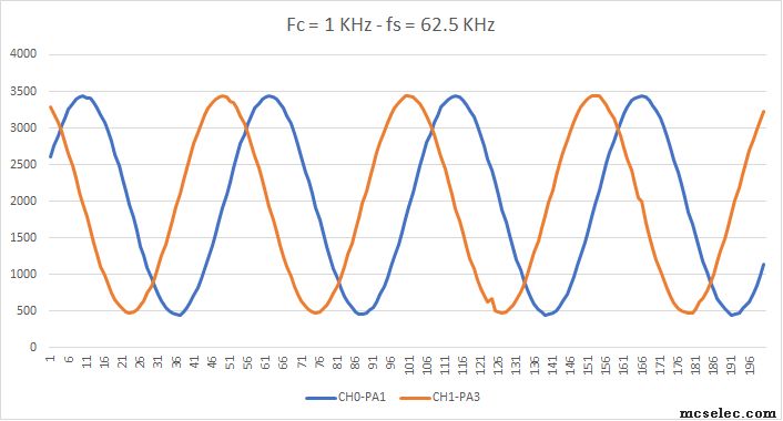
The 62.5 Khz is the sampling frequency limit, if I increase the frequency I will start to loose reading, I think is the limit of the interrupt driven ADC instead of the DMA. |
|
| Back to top |
|
|
MWS
Joined: 22 Aug 2009
Posts: 2335
|
| Posted: Sat Dec 11, 2021 10:55 pm Post subject: |
|
|
| Davide wrote: | | I think is the limit of the interrupt driven ADC instead of the DMA. |
You're wrong, the current limit is ADC conversion time.
Try a lower prescaler, you will loose precision however.
The following will speed up the ISRs a bit, so you will run into this limit a bit later, 1.03µs vs. 3.47µs ISR-time.
| Code: | $regfile = "xm32a4Udef.dat"
$crystal = 32000000 '32MHz
$hwstack = 64
$swstack = 40
$framesize = 40
Const use_ASM_ISR = 1 ' set to 0 for non-ASM
Config Osc = Enabled , 32mhzosc = Enabled
Config Sysclock = 32mhz '--> 32MHz
'Serial Interface to PC
Config Com5 = 115200 , Mode = Asynchroneous , Parity = None , Stopbits = 1 , Databits = 8
Open "COM5:" For Binary As #1
Print #1 , "-----------------START-------------------"
'Config Interrupts
Config Priority = Static , Vector = Application , Lo = Enabled
Const Sample_count = 301
Dim Channel_0(sample_count) As word 'Measurement Array for Channel 0
Dim Channel_1(sample_count) As word 'Measurement Array for Channel 1
Dim Channel_0_ready_bit As Byte
Dim Channel_1_ready_bit As Byte
Dim Channel_0_sample_count As Word
Dim Channel_1_sample_count As Word
Dim X As Word
Config Adca = single , Convmode = unSigned , Resolution = 12bit , Dma = Off , _
Reference = Intvcc , Event_mode = SWEEP , Prescaler = 32 , Sweep = Ch01 , _
Ch0_gain = 1 , Ch0_inp = SINGLE_ENDED , Mux0 = &B00001000 , _
Ch1_gain = 1 , Ch1_inp = SINGLE_ENDED , Mux1 = &B00011000 ,EVENT_CHANNEL=CH0123,
Config TcD0 = Freq , Prescale = 4 , Comparea = Enabled , Resolution = 16
CONFIG EVENT_SYSTEM = dummy, MUX0 = TCD0_OVF ' event channel 0 input for timer 0 overflow
TcD0_cca = &H009f'Timer for sampling the ADC - System Clock/Prescaler(CCA + 1) = 32MHz/4(127 + 1) = 32MHz/4*128 =62.5 Khz
start TcD0
'Here you can check if the Mux Register are written correct !
'Print #1 , "ADCA_CH0_MUXCTRL = " ; Bin(adca_ch0_muxctrl)
'Print #1 , "ADCA_CH1_MUXCTRL = " ; Bin(adca_ch1_muxctrl)
'Print #1 , "Adca_ch0_intctrl = " ; Bin(Adca_ch0_intctrl)
#IF use_ASM_ISR = 1
'Channel 0 Interrupt
On Adca_ch0 Channel_0_ready NOSAVE
'Channel 1 Interrupt
On Adca_ch1 Channel_1_ready NOSAVE
Enable Interrupts
#ELSE
On Adca_ch0 Channel_0_ready
On Adca_ch1 Channel_1_ready
#ENDIF
Enable Adca_ch0 , Lo
Enable Adca_ch1 , Lo
Do
If Channel_0_ready_bit = 1 Then 'Channel 2 conversion complet interrupt ?
Channel_0_ready_bit = 0
Set Adca_ch0_intflags.0 'Clear Int Flag CH 0
Channel_0(channel_0_sample_count) = Adca_ch0_res
End If
If Channel_1_ready_bit = 1 Then 'Channel 2 conversion complet interrupt ?
Channel_1_ready_bit = 0
Set Adca_ch1_intflags.0 'Clear Int Flag CH 0
Channel_1(channel_1_sample_count) = Adca_ch1_res
End If
Loop Until Sample_count = Channel_1_sample_count 'Loop unitl the second Channel is ready
Print #1 , " 300 Sample READY"
'Disable Channel 0 Interrupt on comversion complete
Adca_ch0_intctrl = &B0000_00_00 'OFF Int on Conversion complete (CH 0)
Adca_ch1_intctrl = &B0000_00_00 'OFF Int on Conversion complete (CH 1)
'Disable Free Running mode
Reset Adca_ctrlb.3
'Disable ADC A
Reset Adca_ctrla.0
'Print Results to COM
Print #1,"******* CH0 *********"
For X = 1 To Sample_count -1
Print #1 , Channel_0(x)
Waitms 1
Next
Print #1,"******* CH1 *********"
For X = 1 To Sample_count -1
Print #1 , Channel_1(x)
Waitms 1
Next
End 'end program
#IF use_ASM_ISR = 1
Channel_0_ready:
!PUSH R24
!IN R24, SREG
!PUSH R24
!PUSH R25
!LDS R24, {Channel_0_sample_count}
!LDS R25, {Channel_0_sample_count+1}
!ADIW R24, 1
!STS {Channel_0_sample_count}, R24
!STS {Channel_0_sample_count+1}, R25
!LDI R24, 1
!STS {Channel_0_ready_bit}, R24
!POP R25
!POP R24
!OUT SREG, R24
!POP R24
!RETI
Channel_1_ready:
!PUSH R24
!IN R24, SREG
!PUSH R24
!PUSH R25
!LDS R24, {Channel_1_sample_count}
!LDS R25, {Channel_1_sample_count+1}
!ADIW R24, 1
!STS {Channel_1_sample_count}, R24
!STS {Channel_1_sample_count+1}, R25
!LDI R24, 1
!STS {Channel_1_ready_bit}, R24
!POP R25
!POP R24
!OUT SREG, R24
!POP R24
!RETI
Return
#ELSE
'Channel 0 conversion complete INTERRUPT SERVICE ROUTINE
Channel_0_ready:
Incr Channel_0_sample_count
Set Channel_0_ready_bit
Return
'Channel 1 conversion complete INTERRUPT SERVICE ROUTINE
Channel_1_ready:
Incr Channel_1_sample_count
Set Channel_1_ready_bit
Return
#ENDIF |
|
|
| Back to top |
|
|
Davide
Joined: 25 Sep 2005
Posts: 93
|
| Posted: Sun Dec 12, 2021 4:57 pm Post subject: |
|
|
| Quote: | | The following will speed up the ISRs a bit, so you will run into this limit a bit later, 1.03µs vs. 3.47µs ISR-time. |
Thanks for the code MWS, I had a minor modification to be able to run your code, I enable the interrupts here:
| Code: | Enable Adca_ch0 , Lo
Enable Adca_ch1 , Lo
Enable Interrupts |
I would like to see with a DMA perhaps I can push even more the sampling rate. |
|
| Back to top |
|
|
MWS
Joined: 22 Aug 2009
Posts: 2335
|
| Posted: Sun Dec 12, 2021 5:30 pm Post subject: |
|
|
| Davide wrote: | to be able to run your code, I enable the interrupts here:
| Code: | Enable Adca_ch0 , Lo
Enable Adca_ch1 , Lo
Enable Interrupts |
|
If configured for ASM-mode this should be not required.
But agreed, a tiny flaw in my code. |
|
| Back to top |
|
|
|
|
You cannot post new topics in this forum
You cannot reply to topics in this forum
You cannot edit your posts in this forum
You cannot delete your posts in this forum
You cannot vote in polls in this forum
You cannot attach files in this forum
You cannot download files in this forum
|
|


