| View previous topic :: View next topic |
| Author |
Message |
laborratte
Joined: 27 Jul 2005
Posts: 305
Location: Berlin

|
 Posted: Mon Mar 01, 2021 11:28 am Post subject: Posted: Mon Mar 01, 2021 11:28 am Post subject: |
 |
|
Hi,
A) You are creating a "artifical" 16Bit timer0 with your overflow counter isr and use timer1 as a pwm with a resoultion of 80 (dec) - less than 7 bit. Why not vice versa? When you use timer0 as pwm source you can have the 16bit timer1 without serving an extra overflow counter
B) When working with timer1 anyway you can use in addition the input capture mode like
| Code: |
config timer1= counter, capture_edge=rising, prescale=64
on Capture1 CaptureISR
enable Capture1
start timer1
enable interrupts
do
print Capture1
loop
CaptureISR:
timer1 = 0
return
|
By resetting the timer1 with capture-isr you have in capture1 - register directly the last pulse period in timer1-ticks. No race conditions, no non-atomic problems. You can even enable a hardware filter on input capture or use the analog compare input. |
|
| Back to top |
|
 |
teccs
Joined: 14 Oct 2006
Posts: 69

|
| Posted: Mon Mar 01, 2021 11:57 am Post subject: laborratte |
|
|
Hello laborratte.
Thanks for the reply. I did change the use of Timer0 and Timer 1 around in the second posting of my code. I have not been able to find good material to read so that I can truly understand the timers and pwm. I copied the code in the second posting of my code from the helpful suggestion given by O-Family.
I would love to find a good resource about the timers and pwm. If you have any I can read, please let me know. |
|
| Back to top |
|
|
albertsm
Joined: 09 Apr 2004
Posts: 6201
Location: Holland

|
| Posted: Mon Mar 01, 2021 12:14 pm Post subject: |
|
|
i removed some non technical posts.
private messaging is not activated in this forum. but if some users like to exchange emails to exchange thoughts about non technical matters, let me know in an email.
this forum can however not be used for that.
_________________
Mark |
|
| Back to top |
|
|
O-Family
Joined: 23 May 2010
Posts: 338
Location: Japan

|
| Posted: Mon Mar 01, 2021 1:39 pm Post subject: |
|
|
Hi,
The tachometer program I guided uses a 16-bit Timer1 capture.
This program also accurately measures frequency, period and rotation speed in 32 bits.
However, it may be difficult for you to understand because the articles and program comments on the site are in Japanese.
If you wish, I can translate the comments into English, although it will take some time. |
|
| Back to top |
|
|
laborratte
Joined: 27 Jul 2005
Posts: 305
Location: Berlin
|
| Posted: Mon Mar 01, 2021 2:03 pm Post subject: Re: laborratte |
|
|
| teccs wrote: | | I did change the use of Timer0 and Timer 1 |
sorry, missed that.
| Quote: | | I would love to find a good resource about the timers and pwm. If you have any I can read, please let me know. |
I'm afraid I can't help you - I learned programming microcontrollers with books of Rodnay Zaks and Adam Osborne from the early 1980's - these might be a little outdated. For getting informations about specific features of a controller I usually read the datasheets and the application notes. Of course, most examples are given in C or assembler, so there is a need for understanding these syntax (syntaxes?). |
|
| Back to top |
|
|
EDC
Joined: 26 Mar 2014
Posts: 1136

|
| Posted: Mon Mar 01, 2021 2:07 pm Post subject: |
|
|
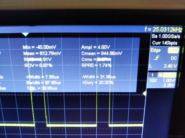
Hello. Take a look on this code. It is based/mixed from those codes -> https://www.mcselec.com/index2.php?option=com_forum&Itemid=59&page=viewtopic&t=14403&highlight=freq+duty.
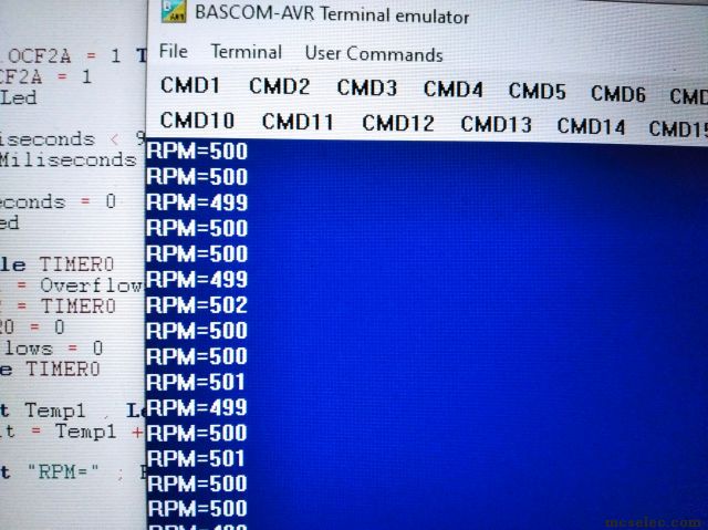
The frequency is aqurate into 25kHz (lok attached pics) and you have opportunity to set Duty from 1 to 99% i think 
In the meaning time uC counts RPM by Timer0 Input pin. Only if it counts more than 256 then interrupt is fired only for counting overflows.
After one second those overflows are Shifted Left 8 because it is 8 bit Timer0. Then rest of Timer0 is added. It measure my generator which I set into 500Hz. I think it measure well
This can be done in another way but maybe this will be sufficient.
Some improvements also can be made here. This is couple of minutes code only. For example Overflows can be even a Byte type cause they are copied into Word later...
| Code: | $regfile = "m328pdef.dat"
$crystal = 16000000
$hwstack=64
$swstack = 16
$framesize = 64
$baud = 115200
Config Submode = New
Config Portb.5 = Output : Led Alias Portb.5 'Arduino Nano LED
Dim Miliseconds As Byte , Value As Word , Overflows As Byte , Result As Word
Dim Temp1 As Word , Temp2 As Word
'** TIMER2 FOR TIME BASE **
Config Timer2 = Timer , Prescale = 1024 , Clear_timer = 1
Compare2a = 155 '10ms @16MHz/1024
'** TIMER1 FOR PWM **
Config Portb.1 = Output 'OC1A pin
'** TIMER0 FOR COUNTING **
Portd.4 = 1 'pullup on T0 pin
Config Timer0 = Counter , Edge = Falling
On Timer0 Timer0_isr ' Nosave
Enable Timer0
'----------------------------------------------------------------
'TCCR1A -> |COM1A1| COM1A0 COM1B1 COM1B0 FOC1A FOC1B WGM11 WGM10 FOR MEGA32 MEGA8
'TCCR1B -> | ICNC1| ICES1 -- WGM13 WGM12 CS12 CS11 CS10
'----------------------------------------------------------------
'----------------------------------------------------------------
'TCCR1A -> |COM1A1 COM1A0 COM1B1 COM1B0 -- -- WGM11 WGM10
'TCCR1B -> | ICNC1 ICES1 -- WGM13 WGM12 CS12 CS11 CS10 FOR MEGA328P
'TCCR1C -> | FOC1A FOC1B -- -- -- -- -- --
'----------------------------------------------------------------
' WGM13-|
Const Pwm_presc1 = &B00010001 'for TCCR1B
Const Pwm_presc8 = &B00010010
Const Pwm_presc64 = &B00010011
Const Pwm_presc256 = &B00010100
Const Pwm_presc1024 = &B00010101
Const Set_output_mode = &B10100000 'for TCCR1A
Tccr1a = Set_output_mode 'set count up, reset count down
Tccr1b = Pwm_presc1 'set prescaler and WGM13
Value = 320 '25kHz
Icr1 = Value
Sub Set_duty(byval Proc As Byte)
Local Help_d As Dword
Local Duty As Word
Help_d = Value * Proc
Help_d = Help_d / 100
Duty = Help_d 'cast DWORD->WORD (was for showing on LCD)
Ocr1a = Duty
End Sub
Call Set_duty(20)
Enable Interrupts
Do
If Tifr2.ocf2a = 1 Then '10ms
Tifr2.ocf2a = 1 'clear the flag
Reset Led
If Miliseconds < 99 Then
Incr Miliseconds
Else '1s period (1Hz)
Miliseconds = 0
Set Led 'LED flash blink 10ms/1s
Disable Timer0
Temp1 = Overflows
Temp2 = Timer0
Timer0 = 0
Overflows = 0
Enable Timer0
Shift Temp1 , Left , 8 'multiply by 256 timer0 cpacity
Result = Temp1 + Temp2
Print "RPM=" ; Result
End If
End If
Loop
End
Timer0_isr:
Incr Overflows
Return
|
[EDIT] I remove assembler block and Nosave command for better clarity. Also Overflows are Byte now,
Last edited by EDC on Mon Mar 01, 2021 7:42 pm; edited 1 time in total |
|
| Back to top |
|
|
SZTRAD
Joined: 30 Dec 2019
Posts: 165
|
| Posted: Mon Mar 01, 2021 7:10 pm Post subject: |
|
|
Hey, EDC
I confess, I don't know how this works.
Timer0 never overflows, so the interrupt doesn't start.
Timer2 won't start at all, or am I wrong? If I remember anything in mathematics, it should apply to speeds of 500 rpm, the frequency is 8.3Hz (500/60). This means that in one second the value of 8 is loaded into Timer0. How you calculated 500 of this value is beyond me. I will also point out that this value needs to be divided by 2. The fan sends 2 signals per revolution (at least the vast majority of them).
I can't seem to keep track of new programming trends.
And I mean, honestly, I really miss how it works.
RS |
|
| Back to top |
|
|
EDC
Joined: 26 Mar 2014
Posts: 1136
|
| Posted: Mon Mar 01, 2021 7:26 pm Post subject: |
|
|
Timer2 or any Timer configured in Bascom dont need command "Start Timer". They start automatically. Command Start Timer is used only if you Stop Timer to start them again. So Timer2 is working for shure but I dont need interrupt from it. I only check its flag.
So for Timer2 I check its TimerInterruptFlagRegister TIFR2 where Timer showing Overflows or CompareA/B Event.
Then I clear the flag by writing One into it (not Zero).
So I can measure the time. 100x 10ms = 1s
Timer0 have special pin on the PORTD.4 (name T0). When Timer0 is configured as a Counter (not Timer) then it counts Falling or Rising edges on this pin. Every of this event is counted till 255 because its 8bit. Only then Overflow appear. So events can be counted without INT0 or INT1 and everytime firing Interrupt. Simply Timer count silently.
Even if overflow will not happen then Timer0 have for example 120 ticks after second and this is Hz (Revolution per Second here)
Now I saw that I name it RPM - my mistake And ofcourse if motor generate two ticks per revolution then simply whole result can be Shift , Right , 1 for divide by two.
Value 500 is from my square wave generator connected into T0 pin to show that uC counts. |
|
| Back to top |
|
|
SZTRAD
Joined: 30 Dec 2019
Posts: 165
|
| Posted: Mon Mar 01, 2021 8:09 pm Post subject: |
|
|
Witam EDC
ja to przeżyłem ponownie i zrozumiałem, ale dopiero po wysłaniu i nie będę masował pytania to nie byłoby fair. Chcę tylko powiedzieć, że to rozwiązanie jest nieprzydatne dla pytającego. Przy niskiej częstotliwości (a on będzie mierzył niską częstotliwość) błąd będzie + -1Hz (co w jego przypadku oznacza błąd 420-540 obr / min). On musi mierzyć długość okresu.
Z Timerem2 masz rację. Ja tak jakoś przyzwyczaiłem się do puszczania sobie wszystkiego sam.

Oops I'm sorry
Hi, EDC I went over it once more and I got it, but after I sent it and I won't delete the query it wouldn't be fair. I just want to say that this solution is useless to the questioner. At a low frequency (and he will measure the low frequency) the error will be +-1Hz (which in his case means an error of 420-540rpm). He has to measure the length of the period.
You're right about Timer2. I'm kind of used to playing everything myself.
RS |
|
| Back to top |
|
|
EDC
Joined: 26 Mar 2014
Posts: 1136
|
| Posted: Mon Mar 01, 2021 8:53 pm Post subject: |
|
|
Yes. I didn't read the whole topic in depth. Maybe this is not the best uC for this job but this can be done.
What are minimum and maximum RPM?
If two impulses are for one revolution then this will be good to measure them both, then add to eachother (or even every new to previous) and then divide by two. This will average eventually disproportion betwen them.
Remember that with Arduino board you dont stuck with 16MHz. You can use Clockdivision = 2 and get 8MHz for example. Then 25kHz can be easy achieve on the 8bit timer with resolution 160 steps with Prescale1. So ICP1 from Timer1 can be used for measure. |
|
| Back to top |
|
|
teccs
Joined: 14 Oct 2006
Posts: 69
|
| Posted: Sat Mar 06, 2021 6:33 am Post subject: Resuming work on this |
|
|
Thank you all again for the replies.
I am going back to the beginning of everyone's comments and working on implementing them and seeing the results.
The suggestions from MWS are where I am starting. I get a undefined variable error when I compile the code below. It is due to a reference to a register. I thought these did not need to be Dimensioned but maybe I am wrong?
| Code: |
' ------------------------------------------------------------------
' 1. Title Block
' Author: Tim Chapman
' Date: 19 February 2021
' Version: 1.0
' File Name: Bathroom cabinet fan controller.bas
' ------------------------------------------------------------------
' 2. Program Description:
' Controls speed of Noctua 120mm fan and receives RPM information from the fan.
' D:\Boating\Skoota 20\Electrical\Fan
' ------------------------------------------------------------------
' 3. Hardware Features:
' ------------------------------------------------------------------
' 4. Pin Assignments Arduino Nano (Arduino Mega 328P-MUR)
' Pin Function I/O Source/Dest Asserted Notes
' Pin 1 D3 PD3/PCINT19/OC2B/INT1 RPM Input from the fan (Green) .
' Pin 2 D4 PD4/PCINT20/XCK/T0
' Pin 3 GND
' Pin 4 VCC
' Pin 5 GND
' Pin 6 VCC
' Pin 7 XTAL1 (PB6/PCINT6/XTAL1/TOSC1) Not connected to Arduino pins.
' Pin 8 XTAL2 (PB7/PCINT7/XTAL2/TOSC2) Not connected to Arduino pins.
' Pin 9 D5 PD5/PCINT21/OC0B/T1
' Pin 10 D6 PD6/(PCINT22/OC0A/AIN0
' Pin 11 D7 PD7/PCINT23/AIN1
' Pin 12 D8 PB0/PCINT0/CLKO/ICP1
' Pin 13 D9 PB1/PCINT1/OC1A PWM Output to Fan (Blue)
' Pin 14 D10 PB2/(PCINT2/SS/OC1B
' Pin 15 D11 PB3/PCINT3/OC2A/MOSI
' Pin 16 D12 PB4/PCINT4/MISO
' Pin 17 D13 PB5/SCK/PCINT5
' Pin 18 AVCC
' Pin 19 A6 ADC6
' Pin 20 AREF
' Pin 21 AGND
' Pin 22 A7 ADC7
' Pin 23 A0 PC0/ADC0/PCINT8
' Pin 24 A1 PC1/ADC1/PCINT9
' Pin 25 A2 PC2/ADC2/PCINT10
' Pin 26 A3 PC3/ADC3/PCINT11
' Pin 27 A4 PC4/ADC4/ADC4/SDA/PCINT12
' Pin 28 A5 PC5/ADC5/ADC5/SCL/PCINT13
' PIN 29 RESET PC6/RESET/PCINT14
' PIN 30 D0 PD0/RXD/PCINT16
' PIN 31 D1 PD1/TXD/PCINT17
' PIN 32 D2 PD2/INT0/PCINT18
' ------------------------------------------------------------------
' 5. Software Features:
' ------------------------------------------------------------------
' 6. Compiler Directives (these tell BASCOM things about our hardware)
$crystal = 16000000 'microcontroller clock frequency
$regfile = "m328pdef.dat" 'the micro being used
$baud = 19200 'serial port baud rate
$hwstack = 80 'Stack numbers were half of current values.
$swstack = 32
$framesize = 64
' ------------------------------------------------------------------
' 7. Declare Subroutines
' ------------------------------------------------------------------
' 8. Hardware Setups
' setup direction of all ports
Config PortB.1 = Output 'Arduino Nano Pin 13 D9 PB1/PCINT1/OC1A
Config PIND.3 = Input 'RPM Input
Config PORTB.5 = Output 'Yellow LED
CONFIG PORTB.0 = Output 'Pin 12 D8 PB0/PCINT0/CLKO/ICP1
CONFIG TIMER0 = TIMER, PRESCALE = 1024 '16 MHz clock / 1024 = 15625 Pulses per second. 15625 pulses per second / 256 = 61.035. That will be how many times Timer2 overflows per second.
On Int1 ISR_Int1
Enable Int1
Config Int1 = Rising
ENABLE TIMER0
ENABLE INTERRUPTS
START TIMER0
On Ovf0 Timer0_isr
' ------------------------------------------------------------------
' 11. Declare Variables
DIM INT1Count AS BYTE
DIM RPM AS SINGLE
DIM Timer0TicksThisRevolution AS BYTE
DIM PulseTime AS SINGLE
DIM Timer0OverflowsSeconds AS SINGLE
DIM Timer0OverflowsThisRevolution AS WORD
DIM Timer0TicksSeconds AS SINGLE
DIM Timer0Overflows AS WORD
DIM Timer0Ticks AS BYTE
Dim Data_Ready As Byte
YellowLED Alias PORTB.5
PIND.3=1 'Turn on pull-up resistor for pin D.1 (T0).
' ------------------------------------------------------------------
' 12. Initialize Variables
'2. Set Timer1 registers to Fast-PWM Mode with ICR1 as TOP Value (Mode 14),Compare A = Clear down:
Tccr1a = &B10000010 'Bit 7:6 COM1A1:0: Compare Output Mode for channel A set to 10
' = Clear OC1A on Compare Match, set OC1A at TOP
'Bit 5:4 COM1B1:0: Compare Output Mode for channel B set to 00
' = Normal port operation, OC1B disconnected.
'Bit 3 FOC1A: Force Output Compare for channel A set to 0 - not used in PWM
'Bit 2 FOC1B: Force Output Compare for channel B set to 0 - not used in PWM
'Bit 1:0 WGM11:0: Waveform Generation Mode set to ..10
' = lower bits of Mode 14: fast PWM; TOP = ICR1
Tccr1b = &B00011010 'Bit 7 ICNC1: Input Capture Noise Canceler set to 0 - not used in PWM
'Bit 6 ICES1: Input Capture Edge Select set to 0 - not used in PWM
'Bit 5 Reserved Bit set to 0
'Bit 4:3 WGM13:2: Waveform Generation Mode set to 11..
' = higher bits of Mode 14: fast PWM; TOP = ICR1
'Bit 2:0 CS12:0: Clock Select set to
' = higher bits of Mode 14: fast PWM; TOP = ICR1
'Bit 2:0 CS12:0: Clock Select set to 010 = clkI/O / 8 (From prescaler)
Icr1 = 80 'This combined with the above makes the Frequency = approximately 25kHz.
'I = 3
Pwm1a = 20 'This sets the duty cycle. Duty Cycle = (Pwm1a-1)*1.2345+2.53
'Do
'pulsein w , PIND , 7 , 0 'detect time from 0 to 1
'print "PulseIn Results = ";w
'Loop
Do
Disable Timer0 ' disable cross-access by timer ISR
If Data_Ready = 1 Then
Timer0TicksThisRevolution = Tmp_T0TTR
Timer0OverflowsThisRevolution = Tmp_T0OTR
Data_Ready = 0
End If
Enable Timer0
Timer0OverflowsSeconds = Timer0OverflowsThisRevolution * 0.016384 'This calculates the Timer 0 overflows portion of the duration of this clock pulse.
Timer0TicksSeconds = Timer0TicksThisRevolution * 0.000064 'This calculates the Timer 0 portion of the duration of this clock pulse.
PulseTime = Timer0OverflowsSeconds + Timer0TicksSeconds 'This adds the two portions of the time measurement together to get the duration of the clock pulse.
RPM = 60.0 / PulseTime 'This is 60 seconds (1 minute) divided by the time for one revolution (in seconds) to give us the number of revolutions in 60 seconds (one minute).
PRINT "Timer0OverflowsThisRevolution = "; Timer0OverflowsThisRevolution
'PRINT "Timer0TicksThisRevolution = "; Timer0TicksThisRevolution
'PRINT "Timer0OverflowsSeconds = "; Timer0OverflowsSeconds
'PRINT "Timer0TicksSeconds = "; Timer0TicksSeconds
'PRINT "PulseTime = "; PulseTime
PRINT "RPM = "; RPM
PRINT ""
WAITMS 1000
Toggle YellowLED
Loop
END 'end program
' - - - - - - - - - - - - - - - - - - - - - - - - - - - - - - - - - - - - - - - - - - - - - - - - - - - - - - - - - - - - - - - - - -
' 15. Subroutines
' ------------------------------------------------------------------
' 16. Interrupts
Timer0_isr: 'Each time Timer0 overflows, this interrupt service routine is called.
INCR Timer0Overflows 'every .01632 seconds.
'PRINT "In Timer0_isr YES"
Return
ISR_Int1: 'Each time the RPM input rises, this interrupt service routine is called.
Timer0Ticks = Timer0 'Timer0 ticks every .000064 seconds which is the 16 MHz clock divided by 1024. We are capturing this as soon as this ISR is called for the greatest accuracy of RPM measurements.
'Timer0Ticks will only actually be used when INT1Count = 2. Then Timer0Ticks is assigned to Timer0TicksThisPulse and used for calculations of RPM.
'To solve a possible race condition: In case ISR Int1 triggers a tiny bit before ISR Timer0 Ovfl does.
'In this case the Timer0 contains already value 0 from overflow, while the var Timer0Overflows can't catch it this turn, means one overflow too less. But for the next measurement, one to many.
'fixed by checking the Timer0 overflow flag within ISR Int1.
'If the flag (TIVR0.TOV0) is set, then add one overflow and clear the flag (and pending interrupt) by writing an 1 to it.
IF TIVR0.TOV0 = 0 THEN
TIVR0.TOV0 = 1
INCR Timer0Overflows
END IF
INCR Int1Count
'Print "In ISR_Int0"
IF INT1Count = 2 THEN 'Counted 2 rising edges from the fan = 2 completed pulses = 1 revolution of the fan.
If Data_Ready = 0 Then
Tmp_T0TTR = Timer0Ticks
Tmp_T0OTR = Timer0Overflows
Data_Ready = 1
END IF
Timer0TicksThisRevolution = Timer0Ticks
Timer0OverflowsThisRevolution = Timer0Overflows
Timer0Overflows = 0
INT1Count = 0
Timer0 = 0
END IF
Return
|
|
|
| Back to top |
|
|
EDC
Joined: 26 Mar 2014
Posts: 1136
|
| Posted: Sat Mar 06, 2021 7:16 am Post subject: |
|
|
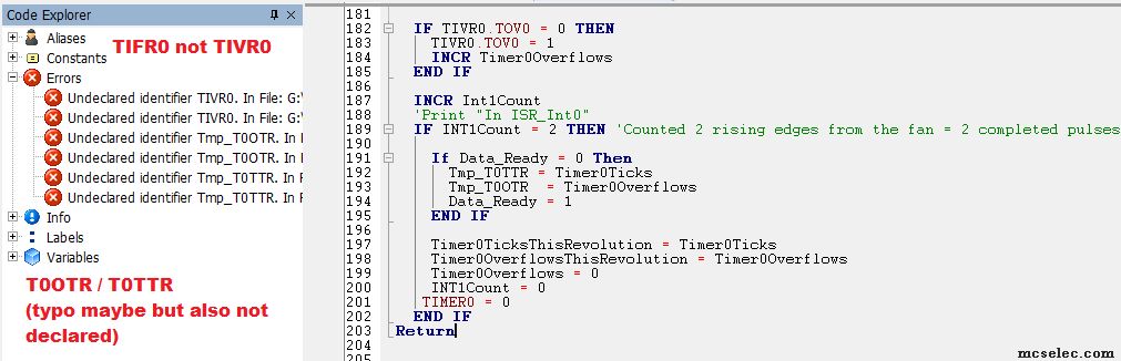
Please enable Code Explorer for runtime code checking during programming.
There are TimerInterruptFlagRegister`s TIFR`s for every timer not TIVR`s.
 |
|
| Back to top |
|
|
SZTRAD
Joined: 30 Dec 2019
Posts: 165
|
| Posted: Sat Mar 06, 2021 12:01 pm Post subject: |
|
|
I took your program and adjusted it a little bit.
I don't have time to compose a real application for testing, but it should probably work. All the settings are yours,so you know what you've been doing.
The difference is you measure the pulse length between the two leading edges.
In this state it should be able to measure up to 1s. The resolution is due to timer0 overflow and amounts to 0.000016s.
If you need to soften it, set some value to timer0, but watch out for Timer0Overflows overflows.
| Code: |
$crystal = 16000000 'microcontroller clock frequency
$regfile = "m328pdef.dat" 'the micro being used
$baud = 19200 'serial port baud rate
$hwstack = 80 'Stack numbers were half of current values.
$swstack = 32
$framesize = 64
' ------------------------------------------------------------------
' 7. Declare Subroutines
' ------------------------------------------------------------------
' 8. Hardware Setups
' setup direction of all ports
Config PortB.1 = Output 'Arduino Nano Pin 13 D9 PB1/PCINT1/OC1A
Config PIND.3 = Input 'RPM Input
Config PORTB.5 = Output 'Yellow LED
CONFIG PORTB.0 = Output 'Pin 12 D8 PB0/PCINT0/CLKO/ICP1
CONFIG TIMER0 = TIMER, PRESCALE = 1 'owerflow (1/16000000)*256=0.000016s
stop timer0
timer0=0
On Int1 ISR_Int1
Enable Int1
Config Int1 = Rising
ENABLE TIMER0
ENABLE INTERRUPTS
On Ovf0 Timer0_isr
' ------------------------------------------------------------------
' 11. Declare Variables
DIM INT1Count AS BYTE
DIM RPM AS SINGLE
DIM Timer0TicksThisRevolution AS single
DIM PulseTime AS SINGLE
DIM Timer0OverflowsSeconds AS SINGLE
DIM Timer0OverflowsThisRevolution AS WORD
DIM Timer0TicksSeconds AS SINGLE
DIM Timer0Overflows AS WORD
DIM Timer0Ticks AS BYTE
DIM ExpectedSpeed AS SINGLE
DIM MaxExpectedSpeed AS SINGLE
DIM PWMIAvar AS BYTE
dim pom_Timer0Overflows as byte
dim pom1_Timer0Overflows as byte
YellowLED Alias PORTB.5
PIND.3=1 'Turn on pull-up resistor for pin D.1 (T0).
' ------------------------------------------------------------------
' 12. Initialize Variables
'2. Set Timer1 registers to Fast-PWM Mode with ICR1 as TOP Value (Mode 14),Compare A = Clear down:
Tccr1a = &B10000010 'Bit 7:6 COM1A1:0: Compare Output Mode for channel A set to 10
' = Clear OC1A on Compare Match, set OC1A at TOP
'Bit 5:4 COM1B1:0: Compare Output Mode for channel B set to 00
' = Normal port operation, OC1B disconnected.
'Bit 3 FOC1A: Force Output Compare for channel A set to 0 - not used in PWM
'Bit 2 FOC1B: Force Output Compare for channel B set to 0 - not used in PWM
'Bit 1:0 WGM11:0: Waveform Generation Mode set to ..10
' = lower bits of Mode 14: fast PWM; TOP = ICR1
Tccr1b = &B00011010 'Bit 7 ICNC1: Input Capture Noise Canceler set to 0 - not used in PWM
'Bit 6 ICES1: Input Capture Edge Select set to 0 - not used in PWM
'Bit 5 Reserved Bit set to 0
'Bit 4:3 WGM13:2: Waveform Generation Mode set to 11..
' = higher bits of Mode 14: fast PWM; TOP = ICR1
'Bit 2:0 CS12:0: Clock Select set to
' = higher bits of Mode 14: fast PWM; TOP = ICR1
'Bit 2:0 CS12:0: Clock Select set to 010 = clkI/O / 8 (From prescaler)
Icr1 = 80 'This combined with the above makes the Frequency = approximately 25kHz.
'I = 3
PWMIAvar = 20
Pwm1a = PWMIAvar 'This sets the duty cycle. Duty Cycle = (Pwm1a-1)*1.2345+2.53
'ExpectedSpeed = PWMIAvar * 20
'MaxExpectedSpeed = ExpectedSpeed * 1.5
PRINT "Max Expected Speed = ";MaxExpectedSpeed
Do
if pom1_Timer0Overflows=1 then
PulseTime=Timer0Overflows*2
Timer0TicksThisRevolution=Timer0Ticks * 0.0000000625 ' Timer0Ticks* (1/(clock crystal/prescaler))
PulseTime=PulseTime* 0.000016 'PulseTime*((1/(clock crystal/prescaler))*256)
PulseTime=PulseTime+ Timer0TicksThisRevolution
rpm=60/Pulsetime
PRINT "RPM = "; RPM
end if
'Timer0OverflowsSeconds = Timer0OverflowsThisRevolution * 0.016384 'This calculates the Timer 0 overflows portion of the duration of this clock pulse.
'Timer0TicksSeconds = Timer0TicksThisRevolution * 0.000064 'This calculates the Timer 0 portion of the duration of this clock pulse.
' PulseTime = Timer0OverflowsSeconds + Timer0TicksSeconds 'This the taddswo portions of the time measurement together to get the duration of the clock pulse.
' RPM = 60.0 / PulseTime 'This is 60 seconds (1 minute) divided by the time for one revolution (in seconds) to give us the number of revolutions in 60 seconds (one minute).
'PRINT "Timer0OverflowsThisRevolution = "; Timer0OverflowsThisRevolution
'PRINT "Timer0TicksThisRevolution = "; Timer0TicksThisRevolution
'PRINT "Timer0OverflowsSeconds = "; Timer0OverflowsSeconds
'PRINT "Timer0TicksSeconds = "; Timer0TicksSeconds
'PRINT "PulseTime = "; PulseTime
'IF RPM < MaxExpectedSpeed THEN
' PRINT "RPM = "; RPM
' PRINT ""
' WAITMS 1000
' Toggle YellowLED
' END IF
Loop
END 'end program
' - - - - - - - - - - - - - - - - - - - - - - - - - - - - - - - - - - - - - - - - - - - - - - - - - - - - - - - - - - - - - - - - - -
' 15. Subroutines
' ------------------------------------------------------------------
' 16. Interrupts
Timer0_isr: 'Each time Timer0 overflows, this interrupt service routine is called.
INCR Timer0Overflows 'every
Return
ISR_Int1: 'Each time the RPM input pulse changes state, this interrupt service routine is called.
if pom_Timer0Overflows=1 then
stop timer0
pom_Timer0Overflows=0
pom1_Timer0Overflows=1
Timer0Ticks = Timer0
else
pom_Timer0Overflows=1
pom1_Timer0Overflows=0
timer0=0
start timer0
end if
Return |
RS |
|
| Back to top |
|
|
teccs
Joined: 14 Oct 2006
Posts: 69
|
| Posted: Mon Mar 08, 2021 10:35 pm Post subject: Still working on the code from NWS |
|
|
I could not get this to work. Results are in attached spreadsheet.
There is a non-linear relationship between the actual RPM from the oscilloscope and the RPM reported by BASCOM.
| Code: |
' ------------------------------------------------------------------
' 1. Title Block
' Author: Tim Chapman
' Date: 19 February 2021
' Version: 1.0
' File Name: Nano. Measures pulse width. Uses NWS suggestions.bas
' ------------------------------------------------------------------
' 2. Program Description:
' Controls speed of Noctua 120mm fan and receives RPM information from the fan.
' D:\Boating\Skoota 20\Electrical\Fan
' Reads rpms high on 3000 rpm fan. Reads high and low 2000 rpm fan.
' ------------------------------------------------------------------
' 3. Hardware Features:
' ------------------------------------------------------------------
' 4. Pin Assignments Arduino Nano (Arduino Mega 328P-MUR)
' Pin Function I/O Source/Dest Asserted Notes
' Pin 1 D3 PD3/PCINT19/OC2B/INT1 PWM Output to Fan (Blue) .
' Pin 2 D4 PD4/PCINT20/XCK/T0
' Pin 3 GND
' Pin 4 VCC
' Pin 5 GND
' Pin 6 VCC
' Pin 7 XTAL1 (PB6/PCINT6/XTAL1/TOSC1) Not connected to Arduino pins.
' Pin 8 XTAL2 (PB7/PCINT7/XTAL2/TOSC2) Not connected to Arduino pins.
' Pin 9 D5 PD5/PCINT21/OC0B/T1
' Pin 10 D6 PD6/(PCINT22/OC0A/AIN0
' Pin 11 D7 PD7/PCINT23/AIN1
' Pin 12 D8 PB0/PCINT0/CLKO/ICP1
' Pin 13 D9 PB1/PCINT1/OC1A
' Pin 14 D10 PB2/(PCINT2/SS/OC1B
' Pin 15 D11 PB3/PCINT3/OC2A/MOSI
' Pin 16 D12 PB4/PCINT4/MISO
' Pin 17 D13 PB5/SCK/PCINT5
' Pin 18 AVCC
' Pin 19 A6 ADC6
' Pin 20 AREF
' Pin 21 AGND
' Pin 22 A7 ADC7
' Pin 23 A0 PC0/ADC0/PCINT8
' Pin 24 A1 PC1/ADC1/PCINT9
' Pin 25 A2 PC2/ADC2/PCINT10
' Pin 26 A3 PC3/ADC3/PCINT11
' Pin 27 A4 PC4/ADC4/ADC4/SDA/PCINT12
' Pin 28 A5 PC5/ADC5/ADC5/SCL/PCINT13
' PIN 29 RESET PC6/RESET/PCINT14
' PIN 30 D0 PD0/RXD/PCINT16
' PIN 31 D1 PD1/TXD/PCINT17
' PIN 32 D2 PD2/INT0/PCINT18 RPM Input from the fan (Green)
' ------------------------------------------------------------------
' 5. Software Features:
' ------------------------------------------------------------------
' 6. Compiler Directives (these tell BASCOM things about our hardware)
$crystal = 16000000 'microcontroller clock frequency
$regfile = "m328pdef.dat" 'the micro being used
$baud = 19200 'serial port baud rate
$hwstack = 80 'Stack numbers were half of current values.
$swstack = 32
$framesize = 64
' ------------------------------------------------------------------
' 7. Declare Subroutines
' ------------------------------------------------------------------
' 8. Hardware Setups
' setup direction of all ports
Config PIND.2 = Input 'RPM Input from the Fan.
Config PORTB.5 = Output 'Yellow LED
CONFIG PORTD.3 = Output 'PWM Output to the fan.
CONFIG TIMER0 = TIMER, PRESCALE = 1024 '16 MHz clock / 1024 = 15625 Pulses per second. 15625 pulses per second. Timer0 overflows every 256 Timer0 ticks or 61.035
'overflows per second.
'That will be an overflow every 0.016384 seconds.
Config Timer2 = Pwm , Prescale = 8 , Clear Timer = 1 , Compare B Pwm = Clear Up '16,000,000Hz / 8 = 2,000,000 Hz
Config Int0 = Rising
Enable Int0
ENABLE TIMER0
'ENABLE TIMER2
ENABLE INTERRUPTS
START TIMER0
'START TIMER2
On Int0 ISR_Int0
On Ovf0 Timer0_isr
' ------------------------------------------------------------------
' 9. Hardware Aliases
YellowLED Alias PORTB.5
' ------------------------------------------------------------------
' 10. Declare Constants
' ------------------------------------------------------------------
' 11. Declare Variables
DIM INT0Count AS BYTE
DIM RPM AS SINGLE
DIM Timer0TicksThisRevolution AS BYTE
DIM PulseTime AS SINGLE
DIM Timer0OverflowsSeconds AS SINGLE
DIM Timer0OverflowsThisRevolution AS BYTE
DIM Timer0TicksSeconds AS SINGLE
DIM Timer0Overflows AS BYTE
DIM Timer0Ticks AS BYTE
Dim Data_Ready As Byte
DIM Tmp_T0TTR AS WORD
DIM Tmp_T0OTR AS WORD
DIM T AS BYTE
DIM RPMTally AS SINGLE
DIM PW AS BYTE
' ------------------------------------------------------------------
' 12. Initialize Variables
Set Tccr2b.wgm02 'Fast PWM Mode. (TOP=OCR2A)
Compare2a = 80 - 1 '2,000,000Hz / 80 = 25,000Hz
'Compare2b = 15 'Pulse width. (Initial value) 78 * 5usec.
' ------------------------------------------------------------------
' 13. Initialize ports so hardware starts correctly
PIND.2=1 'Turn on pull-up resistor for pin D.1 (T0).
' ------------------------------------------------------------------
' 14. Program starts here
DO
FOR PW = 9 to 79
Compare2b = PW
Wait 5
RPMTally = 0
FOR T = 1 TO 10
DISABLE TIMER0 ' disable cross-access by timer ISR
IF Data_Ready = 1 THEN
Timer0TicksThisRevolution = Tmp_T0TTR
Timer0OverflowsThisRevolution = Tmp_T0OTR
Data_Ready = 0
END IF
ENABLE TIMER0
Timer0OverflowsSeconds = Timer0OverflowsThisRevolution * 0.016384 'This calculates the Timer 0 overflows portion of the duration of this clock pulse.
Timer0TicksSeconds = Timer0TicksThisRevolution * 0.000064 'This calculates the Timer 0 portion of the duration of this clock pulse.
PulseTime = Timer0OverflowsSeconds + Timer0TicksSeconds 'This adds the two portions of the time measurement together to get the duration of the clock pulse.
RPM = 60.0 / PulseTime 'This is 60 seconds (1 minute) divided by the time for one revolution (in seconds) to give us the number of revolutions in 60 seconds (one minute).
RPMTally = RPMTally + RPM
'PRINT "Timer0OverflowsThisRevolution = "; Timer0OverflowsThisRevolution
'PRINT "Timer0TicksThisRevolution = "; Timer0TicksThisRevolution
'PRINT "Timer0OverflowsSeconds = "; Timer0OverflowsSeconds
'PRINT "Timer0TicksSeconds = "; Timer0TicksSeconds
'PRINT "PulseTime = "; PulseTime
'PRINT "RPM = "; RPM
'PRINT ""
WAITMS 1000
Toggle YellowLED
NEXT T
RPM = RPMTally / 10.0
PRINT "PW = ";PW
PRINT "RPM = "; RPM
NEXT PW
Loop
END 'end program
' - - - - - - - - - - - - - - - - - - - - - - - - - - - - - - - - - - - - - - - - - - - - - - - - - - - - - - - - - - - - - - - - - -
' 15. Subroutines
' ------------------------------------------------------------------
' 16. Interrupts
Timer0_isr: 'Each time Timer0 overflows, this interrupt service routine is called.
INCR Timer0Overflows 'every .016384 seconds.
'PRINT"Timer0 overflowed";Timer0Overflows
Return
ISR_Int0: 'Each time the RPM input rises, this interrupt service routine is called.
Timer0Ticks = Timer0 'Timer0 ticks every .000064 seconds which is the 16 MHz clock divided by 1024. We are capturing this as soon as this ISR is called for the greatest accuracy of RPM measurements.
'Timer0Ticks will only actually be used when INT0Count = 2. Then Timer0Ticks is assigned to Timer0TicksThisPulse and used for calculations of RPM.
'To solve a possible race condition: In case ISR Int0 triggers a tiny bit before ISR Timer0 Ovfl does.
'In this case the Timer0 contains already value 0 from overflow, while the var Timer0Overflows can't catch it this turn, means one overflow too few.
'But for the next measurement, one too many.
'fixed by checking the Timer0 overflow flag within ISR Int1.
'If the flag (TIVR0.TOV0) is set, then add one overflow and clear the flag (and pending interrupt) by writing an 1 to it.
IF TIFR0.TOV0 = 0 THEN 'Timer 0 overflowed.
TIFR0.TOV0 = 1 'Remove the overflow flag.
INCR Timer0Overflows 'Add one to the overflow count so it is accurate.
END IF
INCR Int0Count
'PRINT "Int0Count = ";Int0Count
IF INT0Count = 2 THEN 'Counted 2 rising edges from the fan = 2 completed pulses = 1 revolution of the fan.
If Data_Ready = 0 Then
Tmp_T0TTR = Timer0Ticks
Tmp_T0OTR = Timer0Overflows
Data_Ready = 1
END IF
'Timer0TicksThisRevolution = Timer0Ticks
'Timer0OverflowsThisRevolution = Timer0Overflows
Timer0Overflows = 0
INT0Count = 0
Timer0 = 0
END IF
Return
|
|
|
| Back to top |
|
|
teccs
Joined: 14 Oct 2006
Posts: 69
|
| Posted: Mon Mar 08, 2021 10:38 pm Post subject: The Code from EDC works |
|
|
So, from there, I tried the code EDC posted above.
It works perfectly.
It reports frequency, not RPM.
RPM = Frequency * 30
So, an error of 1 Hz gives and RPM error of 30 RPM.
That is plenty close enough for fan RPM measurement.
Thank you EDC.
I will go on to the other examples posted by others. |
|
| Back to top |
|
|
|


