| View previous topic :: View next topic |
| Author |
Message |
teccs
Joined: 14 Oct 2006
Posts: 69

|
 Posted: Sat Feb 27, 2021 10:16 am Post subject: Interrupt overflows being missed? Posted: Sat Feb 27, 2021 10:16 am Post subject: Interrupt overflows being missed? |
 |
|
My code posted below is used to control the RPM of a fan and measure the RPM.
It controls the fan speed nicely, but doesn't read the fan speed reliably.
The actual fan RPM is 508 RPM with minor fluctuations.
| Code: |
' 1. Title Block
' Author: Tim Chapman
' Date: 19 February 2021
' Version: 1.0
' File Name: Bathroom cabinet fan controller.bas
' ------------------------------------------------------------------
' 2. Program Description:
' Controls speed of Noctua 120mm fan and receives RPM information from the fan.
' D:\Boating\Skoota 20\Electrical\Fan
' ------------------------------------------------------------------
' 3. Hardware Features:
' ------------------------------------------------------------------
' 4. Pin Assignments Arduino Nano (Arduino Mega 328P-MUR)
' Pin Function I/O Source/Dest Asserted Notes
' Pin 1 D3 PD3/PCINT19/OC2B/INT1 RPM Input from the fan (Green) .
' Pin 2 D4 PD4/PCINT20/XCK/T0
' Pin 3 GND
' Pin 4 VCC
' Pin 5 GND
' Pin 6 VCC
' Pin 7 XTAL1 (PB6/PCINT6/XTAL1/TOSC1) Not connected to Arduino pins.
' Pin 8 XTAL2 (PB7/PCINT7/XTAL2/TOSC2) Not connected to Arduino pins.
' Pin 9 D5 PD5/PCINT21/OC0B/T1
' Pin 10 D6 PD6/(PCINT22/OC0A/AIN0
' Pin 11 D7 PD7/PCINT23/AIN1
' Pin 12 D8 PB0/PCINT0/CLKO/ICP1
' Pin 13 D9 PB1/PCINT1/OC1A PWM Output to Fan (Blue)
' Pin 14 D10 PB2/(PCINT2/SS/OC1B
' Pin 15 D11 PB3/PCINT3/OC2A/MOSI
' Pin 16 D12 PB4/PCINT4/MISO
' Pin 17 D13 PB5/SCK/PCINT5
' Pin 18 AVCC
' Pin 19 A6 ADC6
' Pin 20 AREF
' Pin 21 AGND
' Pin 22 A7 ADC7
' Pin 23 A0 PC0/ADC0/PCINT8
' Pin 24 A1 PC1/ADC1/PCINT9
' Pin 25 A2 PC2/ADC2/PCINT10
' Pin 26 A3 PC3/ADC3/PCINT11
' Pin 27 A4 PC4/ADC4/ADC4/SDA/PCINT12
' Pin 28 A5 PC5/ADC5/ADC5/SCL/PCINT13
' PIN 29 RESET PC6/RESET/PCINT14
' PIN 30 D0 PD0/RXD/PCINT16
' PIN 31 D1 PD1/TXD/PCINT17
' PIN 32 D2 PD2/INT0/PCINT18
' ------------------------------------------------------------------
' 5. Software Features:
' ------------------------------------------------------------------
' 6. Compiler Directives (these tell BASCOM things about our hardware)
$crystal = 16000000 'microcontroller clock frequency
$regfile = "m328pdef.dat" 'the micro being used
$baud = 19200 'serial port baud rate
$hwstack = 80 'Stack numbers were half of current values.
$swstack = 32
$framesize = 64
' ------------------------------------------------------------------
' 7. Declare Subroutines
' ------------------------------------------------------------------
' 8. Hardware Setups
' setup direction of all ports
Config PortB.1 = Output 'Arduino Nano Pin 13 D9 PB1/PCINT1/OC1A
Config PIND.3 = Input 'RPM Input
Config PORTB.5 = Output 'Yellow LED
CONFIG PORTB.0 = Output 'Pin 12 D8 PB0/PCINT0/CLKO/ICP1
CONFIG TIMER0 = TIMER, PRESCALE = 1024 '16 MHz clock / 1024 = 15625 Pulses per second. 15625 pulses per second / 255 = 61.27. That will be how many times Timer2 overflows per second.
On Int1 ISR_Int1
Enable Int1
Config Int1 = Rising
ENABLE TIMER0
ENABLE INTERRUPTS
START TIMER0
On Ovf0 Timer0_isr
' ------------------------------------------------------------------
' 11. Declare Variables
DIM INT1Count AS BYTE
DIM RPM AS SINGLE
DIM Timer0TicksThisRevolution AS BYTE
DIM PulseTime AS SINGLE
DIM Timer0OverflowsSeconds AS SINGLE
DIM Timer0OverflowsThisRevolution AS WORD
DIM Timer0TicksSeconds AS SINGLE
DIM Timer0Overflows AS WORD
DIM Timer0Ticks AS BYTE
YellowLED Alias PORTB.5
PIND.3=1 'Turn on pull-up resistor for pin D.1 (T0).
' ------------------------------------------------------------------
' 12. Initialize Variables
'2. Set Timer1 registers to Fast-PWM Mode with ICR1 as TOP Value (Mode 14),Compare A = Clear down:
Tccr1a = &B10000010 'Bit 7:6 COM1A1:0: Compare Output Mode for channel A set to 10
' = Clear OC1A on Compare Match, set OC1A at TOP
'Bit 5:4 COM1B1:0: Compare Output Mode for channel B set to 00
' = Normal port operation, OC1B disconnected.
'Bit 3 FOC1A: Force Output Compare for channel A set to 0 - not used in PWM
'Bit 2 FOC1B: Force Output Compare for channel B set to 0 - not used in PWM
'Bit 1:0 WGM11:0: Waveform Generation Mode set to ..10
' = lower bits of Mode 14: fast PWM; TOP = ICR1
Tccr1b = &B00011010 'Bit 7 ICNC1: Input Capture Noise Canceler set to 0 - not used in PWM
'Bit 6 ICES1: Input Capture Edge Select set to 0 - not used in PWM
'Bit 5 Reserved Bit set to 0
'Bit 4:3 WGM13:2: Waveform Generation Mode set to 11..
' = higher bits of Mode 14: fast PWM; TOP = ICR1
'Bit 2:0 CS12:0: Clock Select set to
' = higher bits of Mode 14: fast PWM; TOP = ICR1
'Bit 2:0 CS12:0: Clock Select set to 010 = clkI/O / 8 (From prescaler)
Icr1 = 80 'This combined with the above makes the Frequency = approximately 25kHz.
'I = 3
Pwm1a = 20 'This sets the duty cycle. Duty Cycle = (Pwm1a-1)*1.2345+2.53
'Do
'pulsein w , PIND , 7 , 0 'detect time from 0 to 1
'print "PulseIn Results = ";w
'Loop
Do
Timer0OverflowsSeconds = Timer0OverflowsThisRevolution * 0.01632 'This calculates the Timer 0 overflows portion of the duration of this clock pulse.
Timer0TicksSeconds = Timer0TicksThisRevolution * 0.000064 'This calculates the Timer 0 portion of the duration of this clock pulse.
PulseTime = Timer0OverflowsSeconds + Timer0TicksSeconds 'This adds the two portions of the time measurement together to get the duration of the clock pulse.
RPM = 60.0 / PulseTime 'This is 60 seconds (1 minute) divided by the time for one revolution (in seconds) to give us the number of revolutions in 60 seconds (one minute).
PRINT "Timer0OverflowsThisRevolution = "; Timer0OverflowsThisRevolution
'PRINT "Timer0TicksThisRevolution = "; Timer0TicksThisRevolution
'PRINT "Timer0OverflowsSeconds = "; Timer0OverflowsSeconds
'PRINT "Timer0TicksSeconds = "; Timer0TicksSeconds
'PRINT "PulseTime = "; PulseTime
PRINT "RPM = "; RPM
PRINT ""
WAITMS 1000
Toggle YellowLED
Loop
END 'end program
' - - - - - - - - - - - - - - - - - - - - - - - - - - - - - - - - - - - - - - - - - - - - - - - - - - - - - - - - - - - - - - - - - -
' 15. Subroutines
' ------------------------------------------------------------------
' 16. Interrupts
Timer0_isr: 'Each time Timer0 overflows, this interrupt service routine is called.
INCR Timer0Overflows 'every .01632 seconds.
'PRINT "In Timer0_isr YES"
Return
ISR_Int1: 'Each time the RPM input pulse changes state, this interrupt service routine is called.
Timer0Ticks = Timer0 'Timer0 ticks every .000064 seconds which is the 16 MHz clock divided by 1024. We are capturing this as soon as this ISR is called for the greatest accuracy of RPM measurements.
'Timer0Ticks will only actually be used when INT1Count = 2. Then Timer0Ticks is assigned to Timer0TicksThisPulse and used for calculations of RPM.
INCR Int1Count
'Print "In ISR_Int0"
IF INT1Count = 2 THEN 'Counted 2 rising edges from the fan = 2 completed pulses = 1 revolution of the fan.
Timer0TicksThisRevolution = Timer0Ticks
Timer0OverflowsThisRevolution = Timer0Overflows
Timer0Overflows = 0
INT1Count = 0
Timer0 = 0
END IF
Return
|
PWM waveform from Arduino Nano to fan is attached. (PWM Output.jpg)
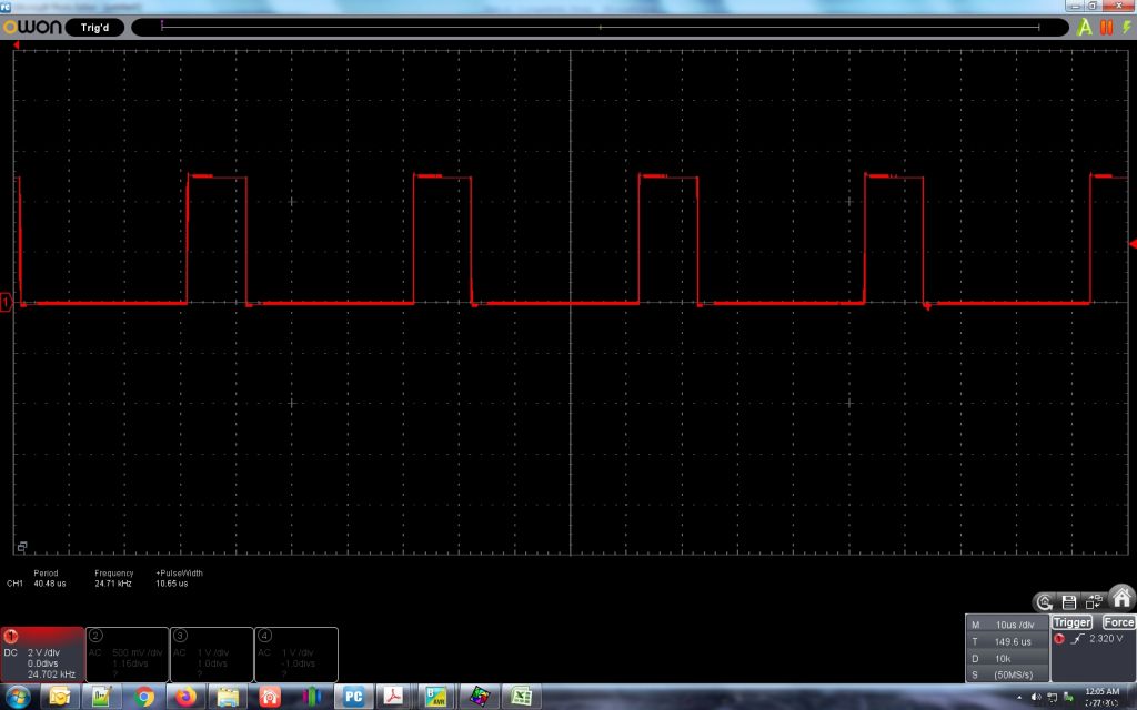
RPM waveform from fan to Arduino Nano is attached. (RPM Input.jpg)
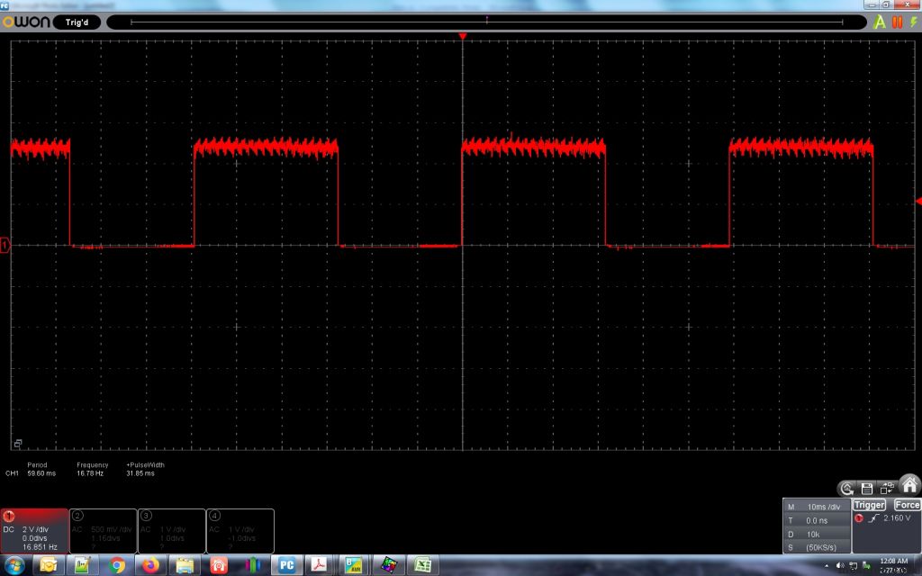
Noise on RPM Waveform is at 24.71 kHz which is the RPM output frequency. I don't think it is causing problems.
The RPM output results and count of Timer0 Overflows for each revolution are shown in Results.jpg.
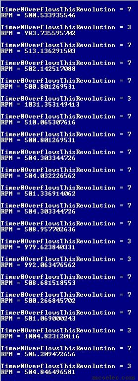
It is missing some TIMER0 overflows when this happens.
I think that is because they are occurring when ISR_Int1 is happening. One interrupt can't occur while another is occurring?
Or the PWM creation is interfering?
(BASCOM-AVR version : 2.0.8.3 ) |
|
| Back to top |
|
 |
Paulvk
Joined: 28 Jul 2006
Posts: 1257
Location: SYDNEY

|
| Posted: Sat Feb 27, 2021 10:21 am Post subject: |
|
|
"One interrupt can't occur while another is occurring"
This is correct. |
|
| Back to top |
|
|
teccs
Joined: 14 Oct 2006
Posts: 69
|
| Posted: Sat Feb 27, 2021 10:27 am Post subject: What is the solution? |
|
|
| Do you know a way to solve the problem or do I need to use two arduinos to do this? |
|
| Back to top |
|
|
Evert :-)
Joined: 18 Feb 2005
Posts: 2156

|
| Posted: Sat Feb 27, 2021 12:04 pm Post subject: |
|
|
As if I understand now you are measuring the time between the 2 edges of the pulse to determine the rpm, not the easiest way.
In the calculations you are also using multiply time singles. Using Singles takes a lot of cpu cycles and I don't think this is atomic so maybe that can also be the reason some times you get strange values.
I think the other way around is easier, counting the number of pulses in a fixed time:
Count with external interrupt the incoming pulses.
Create with timer1 an interrupt every (for example) second and use the counted pulses to calculate the rpm.
_________________
www.evertdekker.com Bascom code vault |
|
| Back to top |
|
|
teccs
Joined: 14 Oct 2006
Posts: 69
|
| Posted: Sat Feb 27, 2021 1:28 pm Post subject: Timer 1 is in use |
|
|
Hi Evert. Thank you for your reply. I could not figure out how to make one of the other timers do the PWM output at the required 25 kHz. If you have a way for me to free up Timer 1 that would be awesome. The acceptable frequency of the PWM signal is 21 kHz to 28 kHz. I need variable duty cycle to be able to control the speed of the with this PWM signal.
I tried first counting pulses using Timer 0 and Timer 2, but the timers are too small with only 8 bits. I will think about making Timer 2 count overflows of Timer 1. That way I might be able to get a big enough count to do some good. |
|
| Back to top |
|
|
O-Family
Joined: 23 May 2010
Posts: 320
Location: Japan

|
|
| Back to top |
|
|
teccs
Joined: 14 Oct 2006
Posts: 69
|
| Posted: Sat Feb 27, 2021 2:18 pm Post subject: How to use Timer0 for 25 kHz PWM with 16 MHz Clock |
|
|
Hi O-Family,
I tried to get 25 kHz out of Timer0 but I could not get it to work.
Do you know how to do it? |
|
| Back to top |
|
|
O-Family
Joined: 23 May 2010
Posts: 320
Location: Japan
|
| Posted: Sat Feb 27, 2021 2:34 pm Post subject: |
|
|
Hi,
For example, a carrier signal is created with Timer2 to create a Timer0 duty pulse.
It is unclear how much PWM signal error is allowed, but since it is software processing by interrupts, PWM signal error will occur. |
|
| Back to top |
|
|
O-Family
Joined: 23 May 2010
Posts: 320
Location: Japan
|
| Posted: Sun Feb 28, 2021 2:04 am Post subject: |
|
|
In your program, the resolution of Timer1 does not seem to be high, so I think it is the same for Timer0.
| Code: | $crystal = 16000000 'microcontroller clock frequency
$regfile = "m328pdef.dat" 'the micro being used
$baud = 19200 'serial port baud rate
$hwstack = 80 'Stack numbers were half of current values.
$swstack = 32
$framesize = 64
Config Portd.5 = Output 'Set the pulse output port [OC0B] to output.
Config Timer0 = Pwm , Prescale = 8 , Clear Timer = 1 , Compare B Pwm = Clear Up '16,000,000Hz / 8 = 2,000,000Hz
Set Tccr0b.wgm02 'Fast PWM Mode. (TOP=OCR0A)
Compare0a = 80 - 1 '2,000,000Hz / 80 = 25,000Hz
Compare0b = 0 'Pulse width. (Initial value) 1-count is 0.5uS.
Dim Pw As Byte 'Declare a variable for the pulse width.
Do
For Pw = 0 To 79 'Change the pulse width from 0.5uS to 40uS.
Compare0b = Pw 'Set the pulse width.
Waitms 50
Next Pw
Loop
End |
|
|
| Back to top |
|
|
MWS
Joined: 22 Aug 2009
Posts: 2262

|
| Posted: Sun Feb 28, 2021 1:29 pm Post subject: |
|
|
The code has several flaws.
First, the comment
| Quote: | | 15625 pulses per second / 255 = 61.27 |
is wrong. 8bits are 256 states, an 8bit-timer has 256 states, as zero is one state too. The calculation must divide by 256.
But's not the true issue why the code is not working.
One and imho the topmost reason is: there is no timed sync between readout-phase and display phase.
Both for the calculation neccessary variables are accessed two times, one time within the ISR where no disturbance will occur, second time where the fault may happen within the calculation within main loop, if in-midst this calculation the ISR Int1 triggers and important input vars for the calculation are altered while the calculation is on the way.
Another problem is non-atomic access of word or bigger than word variables, as the AVR8 processor can only handle 8bit at once, thus several assembler steps are required for one complete assignment from one word to another.
In case any interrupt occurs exactly within this series of assembler code, one byte of the word may restored after ISR-return, while the other is altered.
Last problem this code shows is a possible race-condition, in case ISR Int1 triggers a tiny bit before ISR Timer0 Ovfl does.
In this case the Timer0 contains already value 0 from overflow, while the var Timer0Overflows can't catch it this turn, means one overflow too less. But for the next measurement, one to many.
To fix the asynchronous problem I suggest to use flags, like this:
| Code: | Dim Data_Ready As Byte
'...
Do
Disable Timer0 ' disable cross-access by timer ISR
If Data_Ready = 1 Then
Timer0TicksThisRevolution = Tmp_T0TTR
Timer0OverflowsThisRevolution = Tmp_T0OTR
Data_Ready = 0
End If
Enable Timer0 |
The Disable/Enable block also makes access to Tmp_T0OTR atomic for Timer0 ISR.
If such is desired for all interrupts: Disable/Enable Interrupts or !CLI/!SEI.
...
| Code: | IF INT1Count = 2 THEN
If Data_Ready = 0 Then
Tmp_T0TTR = Timer0Ticks
Tmp_T0OTR = Timer0Overflows
Data_Ready = 1
End If |
It does not solve the race-condition issue, which can be fixed by checking the Timer0 overflow flag within ISR Int1.
If the flag (TIVR0.TOV0) is set, then add one overflow and clear the flag (and pending interrupt) by writing an 1 to it. |
|
| Back to top |
|
|
teccs
Joined: 14 Oct 2006
Posts: 69
|
| Posted: Mon Mar 01, 2021 4:17 am Post subject: The latest |
|
|
Thank you everyone for the replies.
I changed the code to this:
| Code: |
' ------------------------------------------------------------------
' 1. Title Block
' Author: Tim Chapman
' Date: 19 February 2021
' Version: 1.0
' File Name: Bathroom cabinet fan controller.bas
' ------------------------------------------------------------------
' 2. Program Description:
' Controls speed of Noctua 120mm fan and receives RPM information from the fan.
' D:\Boating\Skoota 20\Electrical\Fan
' ------------------------------------------------------------------
' 3. Hardware Features:
' ------------------------------------------------------------------
' 4. Pin Assignments Arduino Nano (Arduino Mega 328P-MUR)
' Pin Function I/O Source/Dest Asserted Notes
' Pin 1 D3 PD3/PCINT19/OC2B/INT1 PWM Output to Fan (Blue)
' Pin 2 D4 PD4/PCINT20/XCK/T0 RPM Input from the fan (Green) .
' Pin 3 GND
' Pin 4 VCC
' Pin 5 GND
' Pin 6 VCC
' Pin 7 XTAL1 (PB6/PCINT6/XTAL1/TOSC1) Not connected to Arduino pins.
' Pin 8 XTAL2 (PB7/PCINT7/XTAL2/TOSC2) Not connected to Arduino pins.
' Pin 9 D5 PD5/PCINT21/OC0B/T1
' Pin 10 D6 PD6/(PCINT22/OC0A/AIN0
' Pin 11 D7 PD7/PCINT23/AIN1
' Pin 12 D8 PB0/PCINT0/CLKO/ICP1
' Pin 13 D9 PB1/PCINT1/OC1A
' Pin 14 D10 PB2/(PCINT2/SS/OC1B
' Pin 15 D11 PB3/PCINT3/OC2A/MOSI
' Pin 16 D12 PB4/PCINT4/MISO
' Pin 17 D13 PB5/SCK/PCINT5
' Pin 18 AVCC
' Pin 19 A6 ADC6
' Pin 20 AREF
' Pin 21 AGND
' Pin 22 A7 ADC7
' Pin 23 A0 PC0/ADC0/PCINT8
' Pin 24 A1 PC1/ADC1/PCINT9
' Pin 25 A2 PC2/ADC2/PCINT10
' Pin 26 A3 PC3/ADC3/PCINT11
' Pin 27 A4 PC4/ADC4/ADC4/SDA/PCINT12
' Pin 28 A5 PC5/ADC5/ADC5/SCL/PCINT13
' PIN 29 RESET PC6/RESET/PCINT14
' PIN 30 D0 PD0/RXD/PCINT16
' PIN 31 D1 PD1/TXD/PCINT17
' PIN 32 D2 PD2/INT0/PCINT18
' ------------------------------------------------------------------
' 5. Software Features:
' ------------------------------------------------------------------
' 6. Compiler Directives (these tell BASCOM things about our hardware)
$crystal = 16000000 'microcontroller clock frequency
$regfile = "m328pdef.dat" 'the micro being used
$baud = 19200 'serial port baud rate
$hwstack = 80 'Stack numbers were half of current values.
$swstack = 32
$framesize = 64
' ------------------------------------------------------------------
' 7. Declare Subroutines
' ------------------------------------------------------------------
' 8. Hardware Setups
' setup direction of all ports
Config PortD.3 = Output 'Arduino Nano OC2B. PWM output to fan (Blue)
Config PIND.4 = Input 'RPM Input T0 (Green).
Config PORTB.5 = Output 'Yellow LED
CONFIG TIMER0 = COUNTER, EDGE = RISING 'Counts RPM Pulses
CONFIG TIMER1 = TIMER, PRESCALE = 1024 '16 MHz clock / 1024 = 15625 Pulses per second.
Config Timer2 = Pwm , Prescale = 8 , Clear Timer = 1 , Compare B Pwm = Clear Up '16,000,000Hz / 8 = 2,000,000Hz
ENABLE TIMER0
ENABLE TIMER2
ENABLE INTERRUPTS
START TIMER0
START TIMER2
On Ovf0 Timer0_isr
On Ovf1 Timer1_isr
' ------------------------------------------------------------------
' 9. Hardware Aliases
YellowLED Alias PORTB.5
' ------------------------------------------------------------------
' 10. Declare Constants
' ------------------------------------------------------------------
' 11. Declare Variables
DIM RPM AS SINGLE
DIM TimeElapsed AS SINGLE
DIM RPS AS SINGLE
DIM Timer1Count AS WORD 'Declare a variable for the pulse width.
' ------------------------------------------------------------------
' 12. Initialize Variables
TIMER0 = 245 'This allows 10 pulses (5 revolutions) to come in before Timer0 overflows. This is to make sure that even at the slowest speed, the duration will be short enough that Timer1 will not overflow.
Set Tccr2b.wgm02 'Fast PWM Mode. (TOP=OCR2A)
Compare2a = 80 - 1 '2,000,000Hz / 80 = 25,000Hz
Compare2b = 15 'Pulse width. (Initial value) 1-count is 0.5uS.
' ------------------------------------------------------------------
' 13. Initialize ports so hardware starts correctly
PIND.4=1 'Turn on pull-up resistor for pin D.1 (T0).
' ------------------------------------------------------------------
' 14. Program starts here
PRINT "HEllo"
DO
IF Timer1Count <> 0 THEN
TimeElapsed = 0.000064 * Timer1Count
RPS = 5.0 / TimeElapsed 'This is because 255 ticks were accumulated in Timer0 before it overflowed. There are 2 ticks per revolution. So the number of revolutions is 128.
RPM = RPS * 60.0
PRINT "RPM = "; RPM
PRINT ""
Timer0 = 245
TIMER1 = 0
Timer1Count = 0
Toggle YellowLED
END IF
LOOP
END 'end program
' - - - - - - - - - - - - - - - - - - - - - - - - - - - - - - - - - - - - - - - - - - - - - - - - - - - - - - - - - - - - - - - - - -
' 15. Subroutines
' ------------------------------------------------------------------
' 16. Interrupts
Timer0_isr: 'Timer0 overflows when 255 pulses have come in from the fan.
Timer1Count = Timer1 'When that happens, capture the Count on Timer1
Return
Timer1_isr:
PRINT"Timer1 is not supposed to ever overflow"
Return
|
With that code, my oscilloscope reports the frequency between 12.16 and 12.31 Hz. That is 364.8 to 369 RPM.
The code has much less accuracy. It reports an average of 349.57 RPM with a low of 331.64 and a high of 417.29 RPM.
It works, but I wish I could get more accuracy out of it. |
|
| Back to top |
|
|
teccs
Joined: 14 Oct 2006
Posts: 69
|
| Posted: Mon Mar 01, 2021 5:00 am Post subject: More accurate with the original code |
|
|
I changed back to the original code with the addition of SAVEALL on the ISRs.
I discarded the RPM readings that were double what normal would be.
I averaged the remaining RPM readings.
Oscilloscope shows an average of
Oscilloscope shows 17.45 Hz which is 523.5 RPM for the low.
17.73 531.9
Oscilloscope shows 17.73 Hz which is 531.9 RPM for the low.
That is an average from the oscilloscope of 527 RPM.
The Arduino Nano reports:
AVG = 529.2614 with the doubled readings removed.
Min = 518.5289
Max = 539.7236
That is much more accurate with the anomalous readings removed. I can make the microcontroller remove the anomalous readings as well and have much better results. This is interesting.
Code is here:
| Code: |
' 1. Title Block
' Author: Tim Chapman
' Date: 19 February 2021
' Version: 1.0
' File Name: Bathroom cabinet fan controller.bas
' ------------------------------------------------------------------
' 2. Program Description:
' Controls speed of Noctua 120mm fan and receives RPM information from the fan.
' D:\Boating\Skoota 20\Electrical\Fan
' ------------------------------------------------------------------
' 3. Hardware Features:
' ------------------------------------------------------------------
' 4. Pin Assignments Arduino Nano (Arduino Mega 328P-MUR)
' Pin Function I/O Source/Dest Asserted Notes
' Pin 1 D3 PD3/PCINT19/OC2B/INT1 RPM Input from the fan (Green) .
' Pin 2 D4 PD4/PCINT20/XCK/T0
' Pin 3 GND
' Pin 4 VCC
' Pin 5 GND
' Pin 6 VCC
' Pin 7 XTAL1 (PB6/PCINT6/XTAL1/TOSC1) Not connected to Arduino pins.
' Pin 8 XTAL2 (PB7/PCINT7/XTAL2/TOSC2) Not connected to Arduino pins.
' Pin 9 D5 PD5/PCINT21/OC0B/T1
' Pin 10 D6 PD6/(PCINT22/OC0A/AIN0
' Pin 11 D7 PD7/PCINT23/AIN1
' Pin 12 D8 PB0/PCINT0/CLKO/ICP1
' Pin 13 D9 PB1/PCINT1/OC1A PWM Output to Fan (Blue)
' Pin 14 D10 PB2/(PCINT2/SS/OC1B
' Pin 15 D11 PB3/PCINT3/OC2A/MOSI
' Pin 16 D12 PB4/PCINT4/MISO
' Pin 17 D13 PB5/SCK/PCINT5
' Pin 18 AVCC
' Pin 19 A6 ADC6
' Pin 20 AREF
' Pin 21 AGND
' Pin 22 A7 ADC7
' Pin 23 A0 PC0/ADC0/PCINT8
' Pin 24 A1 PC1/ADC1/PCINT9
' Pin 25 A2 PC2/ADC2/PCINT10
' Pin 26 A3 PC3/ADC3/PCINT11
' Pin 27 A4 PC4/ADC4/ADC4/SDA/PCINT12
' Pin 28 A5 PC5/ADC5/ADC5/SCL/PCINT13
' PIN 29 RESET PC6/RESET/PCINT14
' PIN 30 D0 PD0/RXD/PCINT16
' PIN 31 D1 PD1/TXD/PCINT17
' PIN 32 D2 PD2/INT0/PCINT18
' ------------------------------------------------------------------
' 5. Software Features:
' ------------------------------------------------------------------
' 6. Compiler Directives (these tell BASCOM things about our hardware)
$crystal = 16000000 'microcontroller clock frequency
$regfile = "m328pdef.dat" 'the micro being used
$baud = 19200 'serial port baud rate
$hwstack = 80 'Stack numbers were half of current values.
$swstack = 32
$framesize = 64
' ------------------------------------------------------------------
' 7. Declare Subroutines
' ------------------------------------------------------------------
' 8. Hardware Setups
' setup direction of all ports
Config PortB.1 = Output 'Arduino Nano Pin 13 D9 PB1/PCINT1/OC1A
Config PIND.3 = Input 'RPM Input
Config PORTB.5 = Output 'Yellow LED
CONFIG PORTB.0 = Output 'Pin 12 D8 PB0/PCINT0/CLKO/ICP1
CONFIG TIMER0 = TIMER, PRESCALE = 1024 '16 MHz clock / 1024 = 15625 Pulses per second. 15625 pulses per second / 256 = 61.035. That will be how many times Timer2 overflows per second.
On Int1 ISR_Int1 SAVEALL
Enable Int1
Config Int1 = Rising
ENABLE TIMER0
ENABLE INTERRUPTS
START TIMER0
On Ovf0 Timer0_isr SAVEALL
' ------------------------------------------------------------------
' 11. Declare Variables
DIM INT1Count AS BYTE
DIM RPM AS SINGLE
DIM Timer0TicksThisRevolution AS BYTE
DIM PulseTime AS SINGLE
DIM Timer0OverflowsSeconds AS SINGLE
DIM Timer0OverflowsThisRevolution AS WORD
DIM Timer0TicksSeconds AS SINGLE
DIM Timer0Overflows AS WORD
DIM Timer0Ticks AS BYTE
YellowLED Alias PORTB.5
PIND.3=1 'Turn on pull-up resistor for pin D.1 (T0).
' ------------------------------------------------------------------
' 12. Initialize Variables
'2. Set Timer1 registers to Fast-PWM Mode with ICR1 as TOP Value (Mode 14),Compare A = Clear down:
Tccr1a = &B10000010 'Bit 7:6 COM1A1:0: Compare Output Mode for channel A set to 10
' = Clear OC1A on Compare Match, set OC1A at TOP
'Bit 5:4 COM1B1:0: Compare Output Mode for channel B set to 00
' = Normal port operation, OC1B disconnected.
'Bit 3 FOC1A: Force Output Compare for channel A set to 0 - not used in PWM
'Bit 2 FOC1B: Force Output Compare for channel B set to 0 - not used in PWM
'Bit 1:0 WGM11:0: Waveform Generation Mode set to ..10
' = lower bits of Mode 14: fast PWM; TOP = ICR1
Tccr1b = &B00011010 'Bit 7 ICNC1: Input Capture Noise Canceler set to 0 - not used in PWM
'Bit 6 ICES1: Input Capture Edge Select set to 0 - not used in PWM
'Bit 5 Reserved Bit set to 0
'Bit 4:3 WGM13:2: Waveform Generation Mode set to 11..
' = higher bits of Mode 14: fast PWM; TOP = ICR1
'Bit 2:0 CS12:0: Clock Select set to
' = higher bits of Mode 14: fast PWM; TOP = ICR1
'Bit 2:0 CS12:0: Clock Select set to 010 = clkI/O / 8 (From prescaler)
Icr1 = 80 'This combined with the above makes the Frequency = approximately 25kHz.
'I = 3
Pwm1a = 20 'This sets the duty cycle. Duty Cycle = (Pwm1a-1)*1.2345+2.53
'Do
'pulsein w , PIND , 7 , 0 'detect time from 0 to 1
'print "PulseIn Results = ";w
'Loop
Do
Timer0OverflowsSeconds = Timer0OverflowsThisRevolution * 0.01632 'This calculates the Timer 0 overflows portion of the duration of this clock pulse.
Timer0TicksSeconds = Timer0TicksThisRevolution * 0.000064 'This calculates the Timer 0 portion of the duration of this clock pulse.
PulseTime = Timer0OverflowsSeconds + Timer0TicksSeconds 'This adds the two portions of the time measurement together to get the duration of the clock pulse.
RPM = 60.0 / PulseTime 'This is 60 seconds (1 minute) divided by the time for one revolution (in seconds) to give us the number of revolutions in 60 seconds (one minute).
PRINT "Timer0OverflowsThisRevolution = "; Timer0OverflowsThisRevolution
'PRINT "Timer0TicksThisRevolution = "; Timer0TicksThisRevolution
'PRINT "Timer0OverflowsSeconds = "; Timer0OverflowsSeconds
'PRINT "Timer0TicksSeconds = "; Timer0TicksSeconds
'PRINT "PulseTime = "; PulseTime
PRINT "RPM = "; RPM
PRINT ""
WAITMS 1000
Toggle YellowLED
Loop
END 'end program
' - - - - - - - - - - - - - - - - - - - - - - - - - - - - - - - - - - - - - - - - - - - - - - - - - - - - - - - - - - - - - - - - - -
' 15. Subroutines
' ------------------------------------------------------------------
' 16. Interrupts
Timer0_isr: 'Each time Timer0 overflows, this interrupt service routine is called.
INCR Timer0Overflows 'every .016384 seconds.
'PRINT "In Timer0_isr YES"
Return
ISR_Int1: 'Each time the RPM input pulse changes state, this interrupt service routine is called.
Timer0Ticks = Timer0 'Timer0 ticks every .000064 seconds which is the 16 MHz clock divided by 1024. We are capturing this as soon as this ISR is called for the greatest accuracy of RPM measurements.
'Timer0Ticks will only actually be used when INT1Count = 2. Then Timer0Ticks is assigned to Timer0TicksThisPulse and used for calculations of RPM.
INCR Int1Count
'Print "In ISR_Int0"
IF INT1Count = 2 THEN 'Counted 2 rising edges from the fan = 2 completed pulses = 1 revolution of the fan.
Timer0TicksThisRevolution = Timer0Ticks
Timer0OverflowsThisRevolution = Timer0Overflows
Timer0Overflows = 0
INT1Count = 0
Timer0 = 0
END IF
Return
|
|
|
| Back to top |
|
|
teccs
Joined: 14 Oct 2006
Posts: 69
|
| Posted: Mon Mar 01, 2021 5:37 am Post subject: Results |
|
|
From the oscilloscope:
Min: 17.03 Hz = 510.9 RPM
Max: 17.33 Hz = 519.9 RPM
Average: 515.4 RPM
From the Arduino Nano:
Average: 518.58 RPM
Min: 505.6636
Max: 536.3272
| Code: |
' 1. Title Block
' Author: Tim Chapman
' Date: 19 February 2021
' Version: 1.0
' File Name: Bathroom cabinet fan controller.bas
' ------------------------------------------------------------------
' 2. Program Description:
' Controls speed of Noctua 120mm fan and receives RPM information from the fan.
' D:\Boating\Skoota 20\Electrical\Fan
' ------------------------------------------------------------------
' 3. Hardware Features:
' ------------------------------------------------------------------
' 4. Pin Assignments Arduino Nano (Arduino Mega 328P-MUR)
' Pin Function I/O Source/Dest Asserted Notes
' Pin 1 D3 PD3/PCINT19/OC2B/INT1 RPM Input from the fan (Green) .
' Pin 2 D4 PD4/PCINT20/XCK/T0
' Pin 3 GND
' Pin 4 VCC
' Pin 5 GND
' Pin 6 VCC
' Pin 7 XTAL1 (PB6/PCINT6/XTAL1/TOSC1) Not connected to Arduino pins.
' Pin 8 XTAL2 (PB7/PCINT7/XTAL2/TOSC2) Not connected to Arduino pins.
' Pin 9 D5 PD5/PCINT21/OC0B/T1
' Pin 10 D6 PD6/(PCINT22/OC0A/AIN0
' Pin 11 D7 PD7/PCINT23/AIN1
' Pin 12 D8 PB0/PCINT0/CLKO/ICP1
' Pin 13 D9 PB1/PCINT1/OC1A PWM Output to Fan (Blue)
' Pin 14 D10 PB2/(PCINT2/SS/OC1B
' Pin 15 D11 PB3/PCINT3/OC2A/MOSI
' Pin 16 D12 PB4/PCINT4/MISO
' Pin 17 D13 PB5/SCK/PCINT5
' Pin 18 AVCC
' Pin 19 A6 ADC6
' Pin 20 AREF
' Pin 21 AGND
' Pin 22 A7 ADC7
' Pin 23 A0 PC0/ADC0/PCINT8
' Pin 24 A1 PC1/ADC1/PCINT9
' Pin 25 A2 PC2/ADC2/PCINT10
' Pin 26 A3 PC3/ADC3/PCINT11
' Pin 27 A4 PC4/ADC4/ADC4/SDA/PCINT12
' Pin 28 A5 PC5/ADC5/ADC5/SCL/PCINT13
' PIN 29 RESET PC6/RESET/PCINT14
' PIN 30 D0 PD0/RXD/PCINT16
' PIN 31 D1 PD1/TXD/PCINT17
' PIN 32 D2 PD2/INT0/PCINT18
' ------------------------------------------------------------------
' 5. Software Features:
' ------------------------------------------------------------------
' 6. Compiler Directives (these tell BASCOM things about our hardware)
$crystal = 16000000 'microcontroller clock frequency
$regfile = "m328pdef.dat" 'the micro being used
$baud = 19200 'serial port baud rate
$hwstack = 80 'Stack numbers were half of current values.
$swstack = 32
$framesize = 64
' ------------------------------------------------------------------
' 7. Declare Subroutines
' ------------------------------------------------------------------
' 8. Hardware Setups
' setup direction of all ports
Config PortB.1 = Output 'Arduino Nano Pin 13 D9 PB1/PCINT1/OC1A
Config PIND.3 = Input 'RPM Input
Config PORTB.5 = Output 'Yellow LED
CONFIG PORTB.0 = Output 'Pin 12 D8 PB0/PCINT0/CLKO/ICP1
CONFIG TIMER0 = TIMER, PRESCALE = 1024 '16 MHz clock / 1024 = 15625 Pulses per second. 15625 pulses per second / 256 = 61.035. That will be how many times Timer2 overflows per second.
On Int1 ISR_Int1 SAVEALL
Enable Int1
Config Int1 = Rising
ENABLE TIMER0
ENABLE INTERRUPTS
START TIMER0
On Ovf0 Timer0_isr SAVEALL
' ------------------------------------------------------------------
' 11. Declare Variables
DIM INT1Count AS BYTE
DIM RPM AS SINGLE
DIM Timer0TicksThisRevolution AS BYTE
DIM PulseTime AS SINGLE
DIM Timer0OverflowsSeconds AS SINGLE
DIM Timer0OverflowsThisRevolution AS WORD
DIM Timer0TicksSeconds AS SINGLE
DIM Timer0Overflows AS WORD
DIM Timer0Ticks AS BYTE
DIM ExpectedSpeed AS SINGLE
DIM MaxExpectedSpeed AS SINGLE
DIM PWMIAvar AS BYTE
YellowLED Alias PORTB.5
PIND.3=1 'Turn on pull-up resistor for pin D.1 (T0).
' ------------------------------------------------------------------
' 12. Initialize Variables
'2. Set Timer1 registers to Fast-PWM Mode with ICR1 as TOP Value (Mode 14),Compare A = Clear down:
Tccr1a = &B10000010 'Bit 7:6 COM1A1:0: Compare Output Mode for channel A set to 10
' = Clear OC1A on Compare Match, set OC1A at TOP
'Bit 5:4 COM1B1:0: Compare Output Mode for channel B set to 00
' = Normal port operation, OC1B disconnected.
'Bit 3 FOC1A: Force Output Compare for channel A set to 0 - not used in PWM
'Bit 2 FOC1B: Force Output Compare for channel B set to 0 - not used in PWM
'Bit 1:0 WGM11:0: Waveform Generation Mode set to ..10
' = lower bits of Mode 14: fast PWM; TOP = ICR1
Tccr1b = &B00011010 'Bit 7 ICNC1: Input Capture Noise Canceler set to 0 - not used in PWM
'Bit 6 ICES1: Input Capture Edge Select set to 0 - not used in PWM
'Bit 5 Reserved Bit set to 0
'Bit 4:3 WGM13:2: Waveform Generation Mode set to 11..
' = higher bits of Mode 14: fast PWM; TOP = ICR1
'Bit 2:0 CS12:0: Clock Select set to
' = higher bits of Mode 14: fast PWM; TOP = ICR1
'Bit 2:0 CS12:0: Clock Select set to 010 = clkI/O / 8 (From prescaler)
Icr1 = 80 'This combined with the above makes the Frequency = approximately 25kHz.
'I = 3
PWMIAvar = 20
Pwm1a = PWMIAvar 'This sets the duty cycle. Duty Cycle = (Pwm1a-1)*1.2345+2.53
ExpectedSpeed = PWMIAvar * 20
MaxExpectedSpeed = ExpectedSpeed * 1.5
PRINT "Max Expected Speed = ";MaxExpectedSpeed
Do
Timer0OverflowsSeconds = Timer0OverflowsThisRevolution * 0.016384 'This calculates the Timer 0 overflows portion of the duration of this clock pulse.
Timer0TicksSeconds = Timer0TicksThisRevolution * 0.000064 'This calculates the Timer 0 portion of the duration of this clock pulse.
PulseTime = Timer0OverflowsSeconds + Timer0TicksSeconds 'This the taddswo portions of the time measurement together to get the duration of the clock pulse.
RPM = 60.0 / PulseTime 'This is 60 seconds (1 minute) divided by the time for one revolution (in seconds) to give us the number of revolutions in 60 seconds (one minute).
'PRINT "Timer0OverflowsThisRevolution = "; Timer0OverflowsThisRevolution
'PRINT "Timer0TicksThisRevolution = "; Timer0TicksThisRevolution
'PRINT "Timer0OverflowsSeconds = "; Timer0OverflowsSeconds
'PRINT "Timer0TicksSeconds = "; Timer0TicksSeconds
'PRINT "PulseTime = "; PulseTime
IF RPM < MaxExpectedSpeed THEN
PRINT "RPM = "; RPM
PRINT ""
WAITMS 1000
Toggle YellowLED
END IF
Loop
END 'end program
' - - - - - - - - - - - - - - - - - - - - - - - - - - - - - - - - - - - - - - - - - - - - - - - - - - - - - - - - - - - - - - - - - -
' 15. Subroutines
' ------------------------------------------------------------------
' 16. Interrupts
Timer0_isr: 'Each time Timer0 overflows, this interrupt service routine is called.
INCR Timer0Overflows 'every .016384 seconds.
'PRINT "In Timer0_isr YES"
Return
ISR_Int1: 'Each time the RPM input pulse changes state, this interrupt service routine is called.
Timer0Ticks = Timer0 'Timer0 ticks every .000064 seconds which is the 16 MHz clock divided by 1024. We are capturing this as soon as this ISR is called for the greatest accuracy of RPM measurements.
'Timer0Ticks will only actually be used when INT1Count = 2. Then Timer0Ticks is assigned to Timer0TicksThisPulse and used for calculations of RPM.
INCR Int1Count
'Print "In ISR_Int0"
IF INT1Count = 2 THEN 'Counted 2 rising edges from the fan = 2 completed pulses = 1 revolution of the fan.
Timer0TicksThisRevolution = Timer0Ticks
Timer0OverflowsThisRevolution = Timer0Overflows
Timer0Overflows = 0
INT1Count = 0
Timer0 = 0
END IF
Return
|
|
|
| Back to top |
|
|
MWS
Joined: 22 Aug 2009
Posts: 2262
|
| Posted: Mon Mar 01, 2021 8:45 am Post subject: Re: Results |
|
|
| teccs wrote: | | Code: | On Int1 ISR_Int1 SAVEALL
On Ovf0 Timer0_isr SAVEALL |
|
SAVEALL is useless here, as the ISRs do not use any register for which the default setting does not take care of.
More exactly: r6, r8-r9, r12-r15 are not saved by default setting, but are not accessed either,
note : moderated, remove some comment |
|
| Back to top |
|
|
albertsm
Joined: 09 Apr 2004
Posts: 5916
Location: Holland
|
| Posted: Mon Mar 01, 2021 10:01 am Post subject: |
|
|
please keep posts about the topic. all other info is not relevant and distracts and even offends. sometimes without realizing.
also notice that some people are more sensitive than others. but except when things are intended to offend, one can also ignore certain remarks.
back to the basic : if you use a variable in both the interrupt and main routine this will end bad. especial for non-bytes. there is an option to treat a variable in a SAFE way : dim sMySingle as single SAFE
the safe (check it in the help) will disable interrupts and re-enable them each time you access the variable.
you can also do this manually, especial when you have to access a lot of variables.
_________________
Mark |
|
| Back to top |
|
|
|
|
You cannot post new topics in this forum
You cannot reply to topics in this forum
You cannot edit your posts in this forum
You cannot delete your posts in this forum
You cannot vote in polls in this forum
You cannot attach files in this forum
You cannot download files in this forum
|
|


