| View previous topic :: View next topic |
| Author |
Message |
dabatek
Joined: 31 Jul 2013
Posts: 32
Location: Serbia

|
 Posted: Wed Oct 30, 2019 9:26 am Post subject: Hardware problem, maybe software solution ? Posted: Wed Oct 30, 2019 9:26 am Post subject: Hardware problem, maybe software solution ? |
 |
|
Hardware problem, maybe software solution ?
I have some control device with lcd 16x2 module and this unit work fine until some inductive load make noise.
After that mcu work fine but lcd make "chinese letters". I know for this problem before and usualy,
I make periodically (e.g 10 minutes) refresh lcd, also when is possible i'l make separate supply, gnd shielding, optocoupler separation.
In some cases I have on lcd module, hardware pull up with 4k7 resistor on db4,5,6,d7, E, and RS line.
RW and db0.1,2,3 are on GND.
Now in this case I don't have possibilty to make changes on hardware, refresh lcd make jobs but
sometimes bad caracters on lcd is not good to wait for new refresh.
My idea for this case is to make this:
| Code: |
'LCD my usualy config
Config Portc.0 = Output 'RW pin usualy i have on port pin for eventualy use lib with active rw
Portc.0=0 ' in this case is on gnd, I dont like lib's with wait because can hold program
' this config in practical use work fine
Config Lcd = 16x2
'Config Lcdbus = 4
'Config Lcdmode = Port
Config Lcdpin = Pin , Db4 = Portc.4 , Db5 = Portc.5 , Db6 = Portc.6 , Db7 = Portc.7 , E = PortD.7 , Rs = Portc.1
Config Lcd = 16x2
INITLCD
cls
Cursor Off,Noblink
waitms 2
Config Portc.4=output 'Now this port pins are config like output *
Config Portc.5=output
Config Portc.6=output
Config Portc.7=output
Config Portd.7=output
Config Portc.1=output
Portc.4=1 'PULL UP *
Portc.5=1
Portc.6=1
Portc.7=1
Portd.7=1
Portc.1=1
'some code:
' LCD command...
Portc.4=1 'After every lcd command
Portc.5=1 'this make pull up on this pins
Portc.6=1 'it is checked with voltmeter
Portc.7=1 ' also work on test board
Portd.7=1
Portc.1=1
'... some code
end |
My question, before I make changes with software on this device, is this solution some source for new problem ?
Thank you.
Z. Dabic
(BASCOM-AVR version : 2.0.8.2 , Latest : 2.0.8.2 ) |
|
| Back to top |
|
 |
MWS
Joined: 22 Aug 2009
Posts: 2335
|
| Posted: Wed Oct 30, 2019 4:48 pm Post subject: Re: Hardware problem, maybe software solution ? |
|
|
| dabatek wrote: | | Code: | Config Lcdpin = Pin , Db4 = Portc.4 , Db5 = Portc.5 , Db6 = Portc.6 , Db7 = Portc.7 , E = PortD.7 , Rs = Portc.1
Portd.7=1 |
|
Doesn't make sense to switch the LCD into ready-mode by pulling Enable high, I rather would pull this pin low after writing to the LCD (if not done already by the driver) and see whether it helps. |
|
| Back to top |
|
|
dabatek
Joined: 31 Jul 2013
Posts: 32
Location: Serbia
|
| Posted: Wed Oct 30, 2019 10:14 pm Post subject: |
|
|
Hi Magic,
Yes you are right, it is much better to leave E pin low, but for db4...db7 pins and RS is good to pull up. |
|
| Back to top |
|
|
AdrianJ
Joined: 16 Jan 2006
Posts: 2483
Location: Queensland

|
| Posted: Wed Oct 30, 2019 11:11 pm Post subject: |
|
|
What you propose might help, but if the LCD ground and processor ground are not closely tied together - in the RF sense - , then noise spikes on one end will still cause problems on the other. I think I would be checking to see where the noise is coming in, and fixing that. Yes I know that a software 'fix' is easier. But it may just make the problem less frequent, which in fact may make it harder to diagnose.
_________________
Adrian Jansen
Computer language is a framework for creativity |
|
| Back to top |
|
|
JC
Joined: 15 Dec 2007
Posts: 627
Location: Cleveland, OH

|
| Posted: Thu Oct 31, 2019 12:49 am Post subject: |
|
|
How far apart is the display from the micro?
JC |
|
| Back to top |
|
|
dabatek
Joined: 31 Jul 2013
Posts: 32
Location: Serbia
|
| Posted: Thu Oct 31, 2019 8:24 am Post subject: |
|
|
In this case I don't have possibility to make some hardware changes, micro is very close to lcd, they share same pcb, track is about 2~3 cm long.
Same controller boards work very good on other places with very strong noise, drive pwm with power fet...
In practical work I have seen that hardware pull up on inputs pins with hi input impedance is much better solution than software pull up.
I'am not shure for this solution, I'll try this "softw. solution"
Thank you. |
|
| Back to top |
|
|
MWS
Joined: 22 Aug 2009
Posts: 2335
|
| Posted: Thu Oct 31, 2019 8:48 am Post subject: |
|
|
| dabatek wrote: | | I have seen that hardware pull up on inputs pins with hi input impedance is much better solution than software pull up. |
There would be another option, switch the data and control pins (except E) to input while the LCD is idle.
Also take care that some displays provide internal pull/up/down resistors, if they are pull down, your pull ups make it worse. |
|
| Back to top |
|
|
EDC
Joined: 26 Mar 2014
Posts: 1136

|
| Posted: Thu Oct 31, 2019 12:27 pm Post subject: |
|
|
@dabatek About your idea. Do you know about new Bascom feature in the Config Lcd? They are "Before" and "After" so Bascom can handle automatically your wanted pin stages.
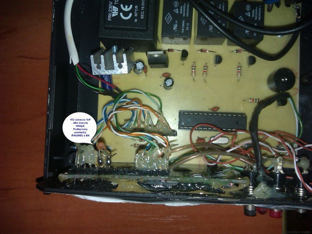
But my post will be about something else. Maybe you find place for small capacitor 1nF/1000pF/102 for solder it betwen EN and GND. This can be SMD...
This solve the LCD problem in that horrible etching contoller I got for free from somebody.
Originally every relay click causes lcd content smash. After my aplaying this capacitor problem was solved.
I know that this board looks horrible. This is not my product. I only add this capacitor and write new software suitted for me 
 |
|
| Back to top |
|
|
dabatek
Joined: 31 Jul 2013
Posts: 32
Location: Serbia
|
| Posted: Thu Oct 31, 2019 7:16 pm Post subject: |
|
|
I apologize for the late reply, I worked all day outside the workshop. I left it working (same type controller like this problematic) on workshop table,
with noise from inductive load. Now with data pins and RS on "softw. pull up". For now after few hour it is OK.
Magic wrote:
| Quote: | | some displays provide internal pull/up/down resistors |
yes it is possible but for this model (luckily) WH1602L1-TMI-CT this solution work
EDC wrote:
| Quote: | | new Bascom feature in the Config Lcd? They are "Before" and "After" |
I don't know for this feature, and of course i will look and try.
For capacitor, yes i know this is good filter method but sometime if pulse is to fast, and we must calculate matching value.
Thanks to everyone who helping for this problem.
After checking (I hope next few days) on real controller. Is this solution work, I will let you know. |
|
| Back to top |
|
|
|
|
You cannot post new topics in this forum
You cannot reply to topics in this forum
You cannot edit your posts in this forum
You cannot delete your posts in this forum
You cannot vote in polls in this forum
You cannot attach files in this forum
You cannot download files in this forum
|
|


