| View previous topic :: View next topic |
| Author |
Message |
jboavida
Joined: 12 Feb 2005
Posts: 94
Location: Portugal

|
 Posted: Fri Jun 24, 2022 8:05 pm Post subject: 1PPS signal Int2 Posted: Fri Jun 24, 2022 8:05 pm Post subject: 1PPS signal Int2 |
 |
|
Hi all,
I'm getting frustrated here...
I'm using a GPS module with 1PPS output to fire an interrupt on ATMEGA324. I'm using INT2
The 1PPS is normally low so I had the interrupt configured for RISING.
Does not work... I tried pull ups, pull downs.... nothing.
In desperation I used an optocupler to invert the signal and configure the interrupt to falling and it works.
I don't want to use optocouplers, because my pcb does not support the hardware and I have several to make.
What i'm missing here?
Thanks
(BASCOM-AVR version : 2.0.8.5 ) |
|
| Back to top |
|
 |
EDC
Joined: 26 Mar 2014
Posts: 971

|
|
| Back to top |
|
|
Evert :-)
Joined: 18 Feb 2005
Posts: 2156

|
|
| Back to top |
|
|
njepsen
Joined: 13 Aug 2007
Posts: 469

|
| Posted: Sat Jun 25, 2022 10:42 pm Post subject: |
|
|
Here is the code I am using to count rain pulses from a rain gauge and wind speed pulses from an anemometer. The wind pulses are 4.8ms wide and can occur several times pe second.
Rain pulse is 20 mS and only x1 every 1 min or so in heavy rain.
The processor is the atmega1284p
| Code: |
'Initialize interrupts for wind input on pin A.4 (PA4, PC Int0)
' rain on PCI3 wind is on PCI4
pcmsk0 = &B00011000 'enable PCI3(rain) and PCI4(wind speed pulse)
PCICR = &B00000001 'enable PC Int0
on PCint0 count_anemometer saveall 'no brackets - must look like a label
'***********************************************
sub count_anemometer()
'rainswitch = tipping bucket rain gauge
if rainswitch = 0 then
if dn15 = 0 then
rainsng = rainsng + rain_bucketsize
Totalrainsng = Totalrainsng + rain_bucketsize 'rain in last 24 hrs
print #1, "rain";Totalrainsng
end if
dn15 = 1
else
dn15 = 0
end if
'windswitch = anemometer lo going, normally hi
if windswitch = 0 then
if dn16 = 0 then
incr windpulsecountw
Toggle Wind_led
end if
dn16 = 1
else
dn16 = 0
end if
end sub
'***************************************
|
_________________
Neil |
|
| Back to top |
|
|
laborratte
Joined: 27 Jul 2005
Posts: 299
Location: Berlin

|
| Posted: Mon Jun 27, 2022 10:49 am Post subject: |
|
|
| How long is the 1PPS pulse of yor GPS Device? At least 50ns is needed for MEGA324A. Maybe your optocoupler works because the pulse is stretched by this relatively slow device. |
|
| Back to top |
|
|
jboavida
Joined: 12 Feb 2005
Posts: 94
Location: Portugal
|
| Posted: Mon Jun 27, 2022 9:51 pm Post subject: |
|
|
Hi All,
Thanks for all the awnsers.
The 1PPS pulse is 100ms.
But, seems that the problem is electronic and not software related.
I have the system powered from 5V and the GPS module is 3.3V, so I have an internal 3.3v regulator to power the GPS
Since the ATMEGA can take logic levels of 3.3V I dind't see a problem. In fact I have several boards that use this same setup (but don't use interrupts) that work just fine.
If the system is powered from 3.3V (atmega and GPS), it works.
I don't understand why. Somebody that knows more electronics than I do please explain... Why rising edge interrupt is sensitive to the voltage diferences.
Thanks |
|
| Back to top |
|
|
njepsen
Joined: 13 Aug 2007
Posts: 469
|
| Posted: Mon Jun 27, 2022 10:13 pm Post subject: |
|
|
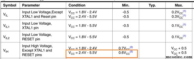
Logic levels is probably your problem. Even though the data sheet says that at Vcc of 5v, 2.6v is treated as logic high and 2.2 is a low, Im wondering if your GPS output is outside this range. Have you tried a weak pullup or pulldown on the mega input that is looking at the GPS signal? What does the pulse look like on a scope?
It is a simple matter to use a FET as a logic level shifter. It is bad practice to mix logic levels.
_________________
Neil |
|
| Back to top |
|
|
EDC
Joined: 26 Mar 2014
Posts: 971
|
| Posted: Mon Jun 27, 2022 10:37 pm Post subject: |
|
|
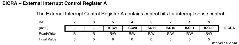
Those are characteristics for Mega324.
0.6Vcc for the 5V power supply not means 0.6V It means 5V * 0.6 = 3V
Some modules have only Open Collector so some pullup must be done but you cant use internal from the Mega because of 5V.
You can try pullup it into 3V3. Or maybe module is 5V I/O tolerant? |
|
| Back to top |
|
|
jboavida
Joined: 12 Feb 2005
Posts: 94
Location: Portugal
|
| Posted: Tue Jun 28, 2022 10:19 am Post subject: |
|
|
Hi,
I did try weak pull ups and pull downs. The only thing that solved the problem was using the same power line (3.3V).
Agree that mixing logic leves is not a good idea. More and more peripherals are becoming 3.3v now. I will change my boards to use only 3.3v.
The only downside I see is that the RS232 and RS485 drivers and the RTC's are much more expensive in 3.3V versions.
Thanks all for the answers. Appreciated.
JB |
|
| Back to top |
|
|
EDC
Joined: 26 Mar 2014
Posts: 971
|
| Posted: Tue Jun 28, 2022 10:26 am Post subject: |
|
|
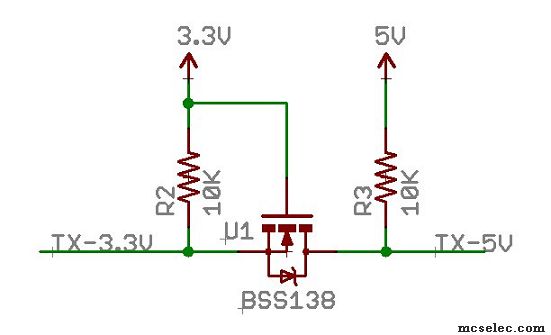
Better try simplest level shifter on that one line. There is toons of similar schematics. Search for "level shifter" or "level converter"
 |
|
| Back to top |
|
|
jenalcom
Joined: 10 Apr 2004
Posts: 365
Location: Perth, Western Australia

|
| Posted: Tue Jun 28, 2022 11:26 am Post subject: |
|
|
| Try putting a diode (or two) in between the output of the GPS and the input to the micro (cathode to the GPS, anode to the micro). This should raise the input voltage on the micro (with a pull up) enough to let it work. |
|
| Back to top |
|
|
JC
Joined: 15 Dec 2007
Posts: 586
Location: Cleveland, OH

|
| Posted: Wed Jun 29, 2022 12:23 am Post subject: |
|
|
Don't forget that the new AVR DB series also has the ability to run on both 3V and 5V at the same time.
One of the ports can run on 3V, with the chip on 5V, and the level conversion is done for you, inside the micro.
The image below shows several peripherals running on 3V, several on 5V.
GLCD, 7-Seg Display, Dallas Temp, Sensirion Temp and %RH, Digital LEDs, LEDs, Piezo, Pot, etc.
JC
JC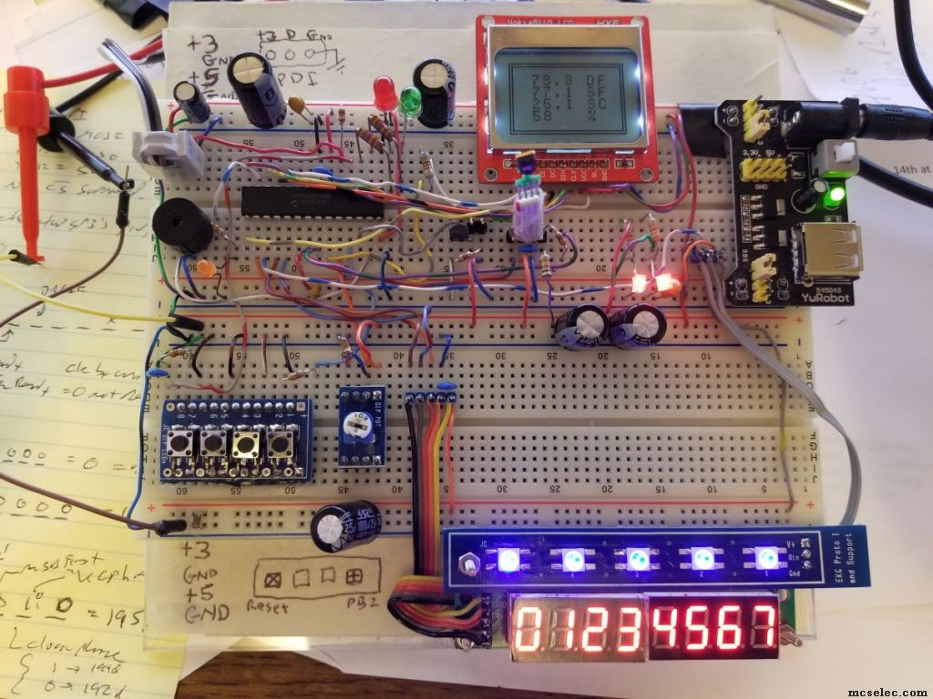 |
|
| Back to top |
|
|
jboavida
Joined: 12 Feb 2005
Posts: 94
Location: Portugal
|
| Posted: Wed Jun 29, 2022 8:59 am Post subject: |
|
|
Nice!
I was in fact considering the DB series for the new design. They have a lot of peripherals. |
|
| Back to top |
|
|
|