| View previous topic :: View next topic |
| Author |
Message |
Per Svensson
Joined: 03 Oct 2004
Posts: 235
Location: Gothenburg, Sweden

|
 Posted: Tue Feb 23, 2021 3:36 pm Post subject: Waveshare 4.2" E-paper display Posted: Tue Feb 23, 2021 3:36 pm Post subject: Waveshare 4.2" E-paper display |
 |
|
Hi
I happened to get two E.-paper displays from Waveshare. One small B/W 2.9" and one bigger B/W/R 4.2"
I also found the excellent work on a lib for the B/W 2.9" display written by Mrshilov
https://www.mcselec.com/index2.php?option=com_forum&Itemid=59&page=viewtopic&t=14057&highlight=epaper
I tried his driver on my display and it worked just fine.
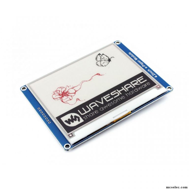
Inspired by this I started to write a driver for the larger display. It has 400x300 pixels and colors Black, White and Red.
https://www.waveshare.com/4.2inch-e-Paper-Module-B.htm
However, it uses a different chip. They are quite differend due to the larger pixelnumber and the three colors
the datasheet for the driver chip IL0389 is very brief so most descriptions need to be gathered from various sources on the net.
Some example code can be obtained from Waveshares site, but unfortunately it is badly commented so it can be hard to see what it does,
and most important why things are done the way they are. All examples are also for the B/W mode only, making it less interesting.
One of the best for explaining how the display works is this one[url] https://benkrasnow.blogspot.com/2017/10/fast-partial-refresh-on-42-e-paper.html[/url] written by Ben
Despite having read all this material, I have not been very successful with this display. I can communicate with it over SPI.
(Reading is not possible. Only write, so it is a bit hard to se what is going on inside the driver chip.)
I can initialize it and fill the entire screen with Black, White or Red , but not in a fully predictable way.
I can also set up for a partial plot of a Box. But also this looks wiered on the screen.
I now feel that some cooperation with a fellow Bascom programmer should be needed to get this finished, so mu question is if someone else have tried this beast,
and how far you have come? Perhaps we can do this together?
Regards
/Per
(BASCOM-AVR version : 2.0.8.3 ) |
|
| Back to top |
|
 |
Per Svensson
Joined: 03 Oct 2004
Posts: 235
Location: Gothenburg, Sweden
|
| Posted: Wed Feb 24, 2021 11:23 am Post subject: |
|
|
Now, much of the initial problems I reported are resolved.
However, there is one thing I cannot wrap my head around.
Display data is always written byte by byte so when setting a certain pixel, one always have to write a whole byte.
Each pixel is represented by one bit within this byte.
This mean that each time you set a pixel by sending a byte you will also destroy the previous pixel if they happen to reside in the same byte. (!)
One remedy would be to read out the already existing byte, modify the desired pixel, and then write it back again.
This method is not possible since the display doesn't allow read mode via SPI. Only write.
Another solution would be to create a shadow pixel map in local (MPU) RAM and the dump the whole pixelmap into the display.
This would mean 300x400/8=15kB of ram use, which is beyond most AVR's capability.
Am I stupid or is this a useless display?
/Per |
|
| Back to top |
|
|
i.dobson
Joined: 05 Jan 2006
Posts: 1570
Location: Basel, Switzerland

|
| Posted: Wed Feb 24, 2021 12:41 pm Post subject: |
|
|
Hi,
If you can't read back the display data, then the only solution is to keep a local copy of the display in host ram or always update the complete display.
The display looks nice, but not really usable for a host with very limited Ram.
Regards
Ian Dobson
_________________
Walking on water and writing software to specification is easy if they're frozen. |
|
| Back to top |
|
|
MWS
Joined: 22 Aug 2009
Posts: 2262

|
| Posted: Wed Feb 24, 2021 1:23 pm Post subject: |
|
|
| Per Svensson wrote: | | Am I stupid or is this a useless display? |
Neither the one nor the other, it simply does not match most of these 8bit processors in standalone configuration, as obviously you need to use a frame buffer.
This frame buffer needs space for - AFAIU - 400 * 300 * 2 (white, red) = 240,000 bits = 30 kByte , which is huge compared to integrated SRam of even the bigger 8bit-AVRs.
The one and only matching type I found was the XMega384C3, which provides 32kBytes SRam, minus 30kByte you are left with 2kByte, which may be enough for your application.
Speed of most of the AVR8s should be the lesser issue, as you won't show videos on such a display, so you may also use smaller controllers and add external SRam.
However you lose then the benefit of using DMA to SPI, the XM384 allows USART in SPI-Master mode to be driven at half IO-speed, 32MHz -> 16MHz.
A screen refresh would take then (400 * 300 * 2) / 16,000,000 = 15ms, which seems fast.
If you use external SRam in combination with a normal Mega@20MHz, you have to add overhead by serving the SPI by user code, let's say 50 optimized cycles per each byte, SPI-in from SRam, preparing registers, SPI-out to the display.
It would need with this overhead of ((400 * 300 * 2) / 8) * 50 = 900,000 cycles @ 20MHz = 75ms. Still good.
Disclaimer: I did not try to understand the method of this display showing white and red, thus if the tiny spheres of them for example get adjusted by providing a voltage for each pixel, or by writing a color- and and address-register for each pixel, means if there are any intermediate steps necessary to convert pixels from the frame buffer into something understood by the display, then you may lose the benefits of DMA.
The final answer to your question is: yes, you can get it to work, but it will take some extra efforts, you need to decide whether it's worth for you. |
|
| Back to top |
|
|
Per Svensson
Joined: 03 Oct 2004
Posts: 235
Location: Gothenburg, Sweden
|
| Posted: Wed Feb 24, 2021 2:16 pm Post subject: |
|
|
Tanks for these insights MWS
One could get away with just one 15 KB buffer end let display operate in only B/W mode.
This could sometimes be acceptable, but also 15kB is a bit too much for most AVRs.
The transfer rate is also a non-issue once you accepted to go for this type of E-paper displays
since a normal refresh takes around 16 seconds. The data dump phase is negligible.
The real killer is this byte adressing.
It would have been better if they also had supported pixel addressing (Even if slower)
Or at least allowed bitmap readback.
Now! - Could there be some workaround? Some clever way of storing not the whole screen locally, or packing the local data in some way?...
Most likely, the screen will not be filled by pixeldata so compression could be acceptable. And due to the slow refresh, the packing/unpacking overhead could be tolerable.
If not - Then I guess I am stuck
/P |
|
| Back to top |
|
|
SZTRAD
Joined: 30 Dec 2019
Posts: 165
|
| Posted: Wed Feb 24, 2021 2:35 pm Post subject: |
|
|
Hi
Search the adafruit_GFX library and GxEPD2 implementation. Try to get inspiration.
It's quite well written and, I think, clearly written.
Since recovery is slow then you can also attach external memory to the SPI to make changes in it and then copy the memory to the display with one override. This would be a viable solution.
RS |
|
| Back to top |
|
|
MWS
Joined: 22 Aug 2009
Posts: 2262
|
| Posted: Wed Feb 24, 2021 3:43 pm Post subject: |
|
|
| Per Svensson wrote: | | The real killer is this byte adressing. |
Maybe you understood something wrong?
What happens if you write &b11111111 into this byte, do you get a piece of a line, or a row?
Assumed a byte represents a piece of line, there must be some way to color the pixels within this byte differently, as otherwise a byte is always of same color.
The picture in your top post already proves the contrary.
As how would pixels of the red rose would be red and how do the non-red pixels know, whether they are white or black? This can't be done within one byte.
Maybe the display works with some OR/AND-mask?
Maybe an extra command setting BG/FG-color for the next byte?
Otherwise let's stay with the 'one byte, one line'-example: simply consider the drawing surface consisting out of 8*8 blocks, width 50 blocks and height 37.5 or the smallest font height.
As your code knows where to write anyway, always stick to this raster. Means develop a certain strategy how to put things to display.
Form follows function. |
|
| Back to top |
|
|
Per Svensson
Joined: 03 Oct 2004
Posts: 235
Location: Gothenburg, Sweden
|
| Posted: Wed Feb 24, 2021 4:05 pm Post subject: |
|
|
Thanks SZTRAD
The GxEPD2 certainly have addressed this problem and are suggesting some interesting tweaks. I have to read it further...
And MWS!
Yes you certainly have a point there when you realise that setting differently colored pixels would be impossible.
I have also thought if this, because in the very interesting video by Ben Krasnow you can hear him stress that "The display will show the difference between buffer 1 and buffer 2".
[url]https://benkrasnow.blogspot.com/2017/10/fast-partial-refresh-on-42-e-paper.html [/url]
At the time I interpreted this as it would only apply in B/W mode. Not in B/W/R mode. In the latter case it is really hard to grasp what the colored difference between the buffers would be.
Unfortunately the datasheet is very very brief (like most chineese data). It does not say much on how the IL0389 chip behaves.
Anyway - As the screen obviously can display detailed pictures in two colors, there must be some way to paint neighbour pixels differently. Even though pixels cannot be addressed separately.
/P |
|
| Back to top |
|
|
Per Svensson
Joined: 03 Oct 2004
Posts: 235
Location: Gothenburg, Sweden
|
| Posted: Wed Feb 24, 2021 5:52 pm Post subject: |
|
|
By some experimenting with filling the two buffers I get the following colors
|-------------- Buffer 1 (B/W control)
| |----------- Buffer 2 (RED contol)
| | COLOR
FF FF = Black
FF 00 = Red
00 00 = White
00 FF = White
Zeoing all bits in Buffer 1 will always generate a white screen irrespective of Buffer 2
So it is not just the diffrence betwen the buffers that defines the color, as
00_FF does not give the same color as FF_00
At least it makes some sense, as Buf1 should control black and white pixels
and Buf2 should control Red pixels.
But what is the definition of a "Not Red "pixel.? Is it Black or Red or perhaps pink?
From the table above it seem that Not Red equals White.
The best would be if one of the white codes above meant "do not change color)". That could be used to
preserve veighbour pixel during byte-write.
I hav to check this up... |
|
| Back to top |
|
|
SZTRAD
Joined: 30 Dec 2019
Posts: 165
|
| Posted: Wed Feb 24, 2021 9:18 pm Post subject: |
|
|
hello
Do you understand the code in "C"?
If you do, I'll wait a few days and try to write it down for AVR so you can bounce back. Unfortunately, it's not on my desk so I won't try it. But you'll be disappointed it's so good for static images. I did it for automatic air quality measurement. Current extraction was an important factor or I wouldn't have used it. I don't speak English well enough to explain. Then perhaps the program will show more. But at least for a kick, register 50 is important to you. And of course register 1 and voltage settings for the displayed layers. And watch the temperature is important register 40.
RS |
|
| Back to top |
|
|
Per Svensson
Joined: 03 Oct 2004
Posts: 235
Location: Gothenburg, Sweden
|
| Posted: Wed Feb 24, 2021 10:24 pm Post subject: |
|
|
After some testing of register combinations I can conclude the following logic:
The two buffers are bit-wise compared and the resulting color are
|-------------- Buffer 1 (B/W control)
| |----------- Buffer 2 (RED contol)
| | COLOR
1 1 = Black
1 0 = Red
0 0 = White
0 1 = White
This mean that red ,white and black colors can exist in the same byte. for instance:
Buf1: 0011 1010
Buf2: 0100 1000
would result in 8 pixels WWRR BWRW
I had hoped that the redundant white combination would have PRESERVED the previous color, but that do not seem to be the case.
So there are two codes for white. What a shame!!!
If my hope had come true the whole problem would have been solved and pixels of all colors could have been plotted independently.
/P |
|
| Back to top |
|
|
MWS
Joined: 22 Aug 2009
Posts: 2262
|
| Posted: Thu Feb 25, 2021 1:23 am Post subject: |
|
|
| Per Svensson wrote: | So there are two codes for white. What a shame!!!
If my hope had come true the whole problem would have been solved and pixels of all colors could have been plotted independently |
These displays use tiny colored balls, which are rotated into the correct positions.
The 4th, in this case unused condition, rotates one pixel-ball into one more color position, while in your display the 4th position is white too.
Technical stuff runs much better with logic than with hope. 
In case you don't want to swap the controller, I'd add a 23K256 to get all the memory needed for the frame buffer.
Or squeeze a FM25V02A in, the frame buffer will even keep its content then at power off..
Both memories are comparably cheap, require only 5 wires and some additional code. |
|
| Back to top |
|
|
SZTRAD
Joined: 30 Dec 2019
Posts: 165
|
| Posted: Thu Feb 25, 2021 2:42 pm Post subject: |
|
|
Hi
It works a little differently in color mode, but it doesn't matter now.
Depending on what you enter in registry 0 for BWR, then set the combination of VBD,DDX and CDI in registry 50. It controls the alternating voltage on the pixel control electrodes. |
|
| Back to top |
|
|
Per Svensson
Joined: 03 Oct 2004
Posts: 235
Location: Gothenburg, Sweden
|
| Posted: Thu Feb 25, 2021 3:22 pm Post subject: |
|
|
Some further experiment reveals that:
| Code: | Color codes when writing to pixel buffers 1 and 2:
'Dash mean that we skip writing to this register
' |-------------- Buffer 1 (B/W control)
' | |----------- Buffer 2 (RED control)
' | | COLOR
' 1 0 = Black
' 1 1 = Red
' 0 0 = White
' 0 1 = Red2
' 0 - = Black -> White , Red -> Red2 , White and Red2 are preserved
' 1 - = White -> Black , Red2 -> Red , Black and Red are preserved
' - 0 = Red -> Black , Red2 -> White , Black and White are preserved
' - 1 = Black -> Red , White -> Red2 , Red and Red2 are preserved
'The table above imply that a single pixel can be set without affecting its neighbors:
'From a pure Black screen White pixels can be added by writing 0 to Buffer 1
'From a pure White screen Black pixels can be added by writing 1 to Buffer 1
'From a pure Red screen Black pixels can be added by writing 0 to Buffer 2
'From a pure Black screen Red pixels can be added by writing 1 to Buffer 2
'Observe that changing White <-> Red and Red2 <-> Black is not possible
'
' -------------- State transition diagram -------------------
' (XX) = Content in Buf1 and Buf2
' Bn=X = Transition due to bit write into Buf1 respective Buf2
'
' ------------- --------------
' /-->--| |------- B2=0 ---->| |-->--\
' B1=0 or | RED2 | | WHITE | B1=0 or
' B2=1 | (01) |<------ B2=1 -----| (00) | B2=0
' \--<--| | | |--<--/
' ------------- --------------
' ^ | ^ |
' | | | |
' B1=0 | | B1=1
' | B1=1 B1=0 |
' | | | |
' | V | V
' ------------- --------------
' /-->--| | | |-->--\
' B1=1 or | RED |------ B2=0 ----->| BLACK | B1=1 or
' B2=1 | (11) | | (10) | B2=0
' \--<--| |<----- B2=1-------| |--<--/
' ------------- -------------- |
So it should be possible to change a White Pixel into a Black and vice versa without affecting red pixels (because Red and Red2 look the same)
Swapping of Red and Black pixels is also possible, but this would also swap Red2 and White pixels as an undesirable side effect.
Changing Red to White or Black to Red2 is not possible without first passing through an intermediate state.
It all mean that if used as a pure B/W display (skipping red) it should be possible to set discrete pixels even when these are clustered within a byte
Perhaps I will spend some time to write code for this.
Perhaps it is not worth it.
He ho lives will se...
/Per |
|
| Back to top |
|
|
|
|
You cannot post new topics in this forum
You cannot reply to topics in this forum
You cannot edit your posts in this forum
You cannot delete your posts in this forum
You cannot vote in polls in this forum
You cannot attach files in this forum
You cannot download files in this forum
|
|


