| View previous topic :: View next topic |
| Author |
Message |
albertsm
Joined: 09 Apr 2004
Posts: 5921
Location: Holland

|
 Posted: Fri Jan 08, 2021 10:26 pm Post subject: Posted: Fri Jan 08, 2021 10:26 pm Post subject: |
 |
|
with an ohm meter measure all GND and VCC/AVCC pins (with power off) and see if they are all actually connected !
this means : are all GND pins actually connected to ground.
are all vcc and avcc pins connected to your vcc power?
then check in volt mode again with power applied and see if the levels are ok.
also : which casing are you using? Does it match the datasheet/cad circuit?
some casing have different pinning.
_________________
Mark |
|
| Back to top |
|
 |
Printpix52
Joined: 18 Jun 2014
Posts: 282
Location: D.F.

|
| Posted: Sat Jan 09, 2021 12:20 am Post subject: |
|
|
I think the problem is the LED resistor replaced by 82 ohms.  |
|
| Back to top |
|
|
Printpix52
Joined: 18 Jun 2014
Posts: 282
Location: D.F.
|
|
| Back to top |
|
|
SZTRAD
Joined: 30 Dec 2019
Posts: 165
|
| Posted: Sat Jan 09, 2021 9:51 am Post subject: |
|
|
I would be very careful with that.
I recommend reading the electrical characteristics in the data sheet. |
|
| Back to top |
|
|
hgrueneis
Joined: 04 Apr 2009
Posts: 902
Location: A-4786 Brunnenthal

|
| Posted: Sat Jan 09, 2021 3:30 pm Post subject: |
|
|
You loaded the chip with the leds without connecting all power pins.
I suspect that one or more internal power lines are blown, maybe also the output buffers.
I would try an other chip.
Regards
Hubert |
|
| Back to top |
|
|
hgrueneis
Joined: 04 Apr 2009
Posts: 902
Location: A-4786 Brunnenthal
|
| Posted: Sat Jan 09, 2021 3:36 pm Post subject: |
|
|
I do not think that an 82 ohm resistor would be the problem, since most leds require 1.5 to 3 volts to light up.
Regards
Hubert |
|
| Back to top |
|
|
SZTRAD
Joined: 30 Dec 2019
Posts: 165
|
| Posted: Sat Jan 09, 2021 3:49 pm Post subject: |
|
|
This is the standard approach of the programmer and not the person who does the HW.
I did not draw attention to the voltage but to the current. These 4 LEDs almost reach the limit of the chip used.
The disappointment is then terribly great when the chip is smoked. Forget the many connections with arduino and read the data sheets. If nothing else, at least the supply voltage and maximum current. Sometimes try to measure the short circuit current of the port and you will understand. |
|
| Back to top |
|
|
enniom
Joined: 20 Oct 2009
Posts: 537
|
| Posted: Sat Jan 09, 2021 6:01 pm Post subject: |
|
|
Tim,
One last guess ...
From the symptoms you describe, it may be possible that the PUD is set.
From the datasheet:
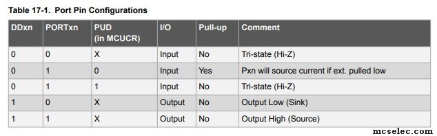
PRINT out the value of MCUCR.PUD to see if it equals 0.
Also note that unlike the Mega328P, the Mega328PB has a JTAG interface with a corresponding fuse bit. Make sure that it is disabled. It is not clear from the datasheet which pins are affected, but its possible that the JTAG overlays on the SPI pins.
If the JTAG is set, bit 7 of the MCUCR register should be 1.
E |
|
| Back to top |
|
|
TSEYFARTH
Joined: 01 Jul 2006
Posts: 1054

|
| Posted: Tue Jan 26, 2021 10:15 pm Post subject: |
|
|
Found the problem!
It was running too fast - 16MHz. The max on 3.3v is 10MHz. Using divide by 8 fuse and quick change to the code corrected the problem.
Thought I'd let everyone know...
Thank you for all of the suggestions and help!
Tim |
|
| Back to top |
|
|
|


