| View previous topic :: View next topic |
| Author |
Message |
TSEYFARTH
Joined: 01 Jul 2006
Posts: 1054

|
|
| Back to top |
|
 |
TSEYFARTH
Joined: 01 Jul 2006
Posts: 1054
|
 Posted: Thu Jan 07, 2021 2:39 am Post subject: Posted: Thu Jan 07, 2021 2:39 am Post subject: |
 |
|
I've also tried with an ATMEGA88 - which is pin compatible, at least for the pins I am using!
Still no good.
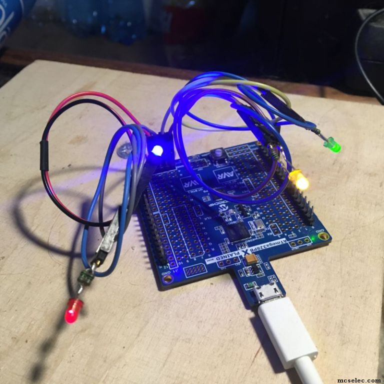
If I bypass the uC and bring ground to the LED, it does turn on, but will not turn on with the uC.
Any help/ideas would be appreciated!
Thank you,
Tim |
|
| Back to top |
|
|
Printpix52
Joined: 18 Jun 2014
Posts: 282
Location: D.F.

|
|
| Back to top |
|
|
enniom
Joined: 20 Oct 2009
Posts: 537
|
| Posted: Thu Jan 07, 2021 3:22 am Post subject: |
|
|
| Code: |
Config BT_Snddataled = Output 'Input
|
Input?
LED powered from 3v3?
E
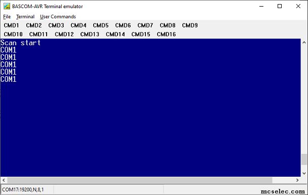
[PS: is it COM1 or COM0? ] |
|
| Back to top |
|
|
EDC
Joined: 26 Mar 2014
Posts: 971

|
| Posted: Thu Jan 07, 2021 9:32 am Post subject: |
|
|
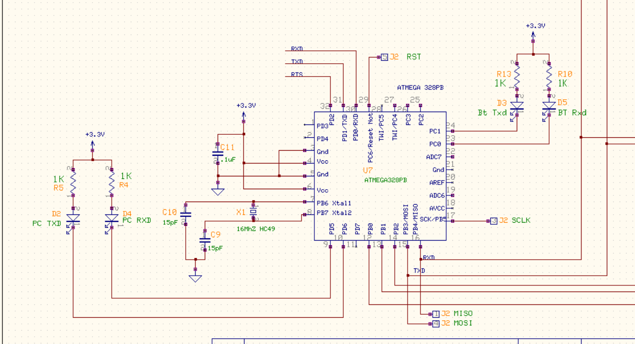
Why not to ground pin 21 on the schematic? 
Your code copied from this forum is working -> see pics.
Last edited by EDC on Thu Jan 07, 2021 10:08 am; edited 1 time in total |
|
| Back to top |
|
|
albertsm
Joined: 09 Apr 2004
Posts: 5915
Location: Holland

|
| Posted: Thu Jan 07, 2021 9:36 am Post subject: |
|
|
avcc seems unconnected.
when searching for problems :
- check short circuit between gnd and vcc but since the firmware programs that should be no problem
- check short circuit on the output pin
- check voltage. simple way is to to use 2 led with one led reverse connected. and of course with a series resistor
then it is important that the good way to connect is as you did between vcc and the port : making a port pin low will make the led light
of course new avr also allow to connect between the port pin and gnd : making a port pin high will make the led light
the total mA a port/processor can draw you can find in the datasheet.
since that is all ok i assume that avcc is the problem.
you can also do the simple test :
| Code: | config portd.5=output
do
toggle portd.5
waitms 1000
loop |
_________________
Mark |
|
| Back to top |
|
|
albertsm
Joined: 09 Apr 2004
Posts: 5915
Location: Holland
|
| Posted: Thu Jan 07, 2021 9:38 am Post subject: |
|
|
| EDC wrote: | | Why not to ground pin 21 on the schematic? |
haha, yes that is essential.
basically ; when the simple led program does not work : check your hardware
_________________
Mark |
|
| Back to top |
|
|
SZTRAD
Joined: 30 Dec 2019
Posts: 165
|
| Posted: Thu Jan 07, 2021 11:20 am Post subject: |
|
|
Unfortunately I don't have AT328PB connected here, but all other atmegs have internally connected GND.
I'm not saying they shouldn't get involved.
A fellow interviewer did not write if the transfer to COM works for him. If not, his chip isn't working. If so, RESET is active (externally or internally).
Last edited by SZTRAD on Thu Jan 07, 2021 1:02 pm; edited 1 time in total |
|
| Back to top |
|
|
hgrueneis
Joined: 04 Apr 2009
Posts: 902
Location: A-4786 Brunnenthal

|
| Posted: Thu Jan 07, 2021 12:51 pm Post subject: |
|
|
A 10K pullup on the RESET might also be helpful.
Regards
Hubert |
|
| Back to top |
|
|
MWS
Joined: 22 Aug 2009
Posts: 2262
|
| Posted: Thu Jan 07, 2021 5:34 pm Post subject: |
|
|
| And don't use blue or white Leds with a VCC of 3.3V ;D |
|
| Back to top |
|
|
hgrueneis
Joined: 04 Apr 2009
Posts: 902
Location: A-4786 Brunnenthal
|
| Posted: Thu Jan 07, 2021 7:19 pm Post subject: |
|
|
If you doubt all the help , that very experienced people give you here, then you should go somewhere else.
You do not even attend to the bare essentials of the electronic requirement for these processors.
My advice, study the datasheets and the Bascom Help. When you are through with that and you still have problems, come back here.
Otherwise "Good luck"
Regards
Hubert |
|
| Back to top |
|
|
TSEYFARTH
Joined: 01 Jul 2006
Posts: 1054
|
| Posted: Thu Jan 07, 2021 9:18 pm Post subject: |
|
|
Hello all and THANK YOU for all of your helpful responses!
I'm trying the suggestions and will get back with you all.
Thank you again,
Tim |
|
| Back to top |
|
|
Duval JP
Joined: 22 Jun 2004
Posts: 1161
Location: France

|
| Posted: Fri Jan 08, 2021 11:34 am Post subject: |
|
|
a scope is a a good friend 
jp
_________________
pleasure to learn, to teach, to create |
|
| Back to top |
|
|
TSEYFARTH
Joined: 01 Jul 2006
Posts: 1054
|
| Posted: Fri Jan 08, 2021 10:06 pm Post subject: |
|
|
Checked with a scope and meter. The pins at the uC stay at 1.7 Volts. They never go to a true hi (3.3) or low.
Other than what has been suggested already, anything else to look at?
Thanks all!
Tim |
|
| Back to top |
|
|
TSEYFARTH
Joined: 01 Jul 2006
Posts: 1054
|
| Posted: Fri Jan 08, 2021 10:15 pm Post subject: |
|
|
Also tried toggling a spare set of pins that are not connected to anything. According to the scope, they stayed low and never changed.
Must be something with the PCB or chip? It programs fine so the xtal should be OK, all of the power and grounds are set up now.It is getting 3.3V.
I've never had a situation where the chip did not respond properly.
Any ideas?
Tim
| Code: |
$regfile = "m328pbdef.dat"
$crystal = 16000000
$baud = 19200
$hwstack = 40
$swstack = 40
$framesize = 40
config portd.5=output
config portd.3=output
config portd.4=output
do
toggle portd.3
toggle portd.4
toggle portd.5
waitms 1000
loop
|
|
|
| Back to top |
|
|
|