| View previous topic :: View next topic |
| Author |
Message |
SZTRAD
Joined: 30 Dec 2019
Posts: 165

|
 Posted: Tue Jul 21, 2020 4:36 pm Post subject: UPDI Posted: Tue Jul 21, 2020 4:36 pm Post subject: UPDI |
 |
|
When trying to program the UPDI chip attiny1604,1606 with the usb converter ch340, it will not connect. After about 60 s, the programmer window closes and when the IDE is closed it reports (see fig.)
All attempts to transmit from Bascom end in error. The waveform on the oscilloscope corresponds to the transmission but the processor does not respond. Has anyone encountered this? I'll try the logic analyzer tomorrow.
(BASCOM-AVR version : 2.0.8.3 , Latest : 2.0.8.3 ) |
|
| Back to top |
|
 |
Memen
Joined: 06 May 2016
Posts: 13
|
| Posted: Tue Jul 21, 2020 7:17 pm Post subject: |
|
|
FTDI, Prolific - tested -ok.
ch340 - tested - bad. |
|
| Back to top |
|
|
albertsm
Joined: 09 Apr 2004
Posts: 5921
Location: Holland
|
| Posted: Tue Jul 21, 2020 8:15 pm Post subject: |
|
|
often usb drivers gave blue screens. so i always start using a normal COM port. (of course even the normal one uses a driver).
you might want to try to update your driver. the time comm drivers gave BS is long time ago.
during development i once in a while had a communication problem. but when you are patient, it should work out.
when there is no comm. you need to recycle the power of the chip. i tested with various tiny816, but i expect the other xtiny will work the same.
_________________
Mark |
|
| Back to top |
|
|
Paulvk
Joined: 28 Jul 2006
Posts: 1257
Location: SYDNEY

|
| Posted: Tue Jul 21, 2020 11:37 pm Post subject: |
|
|
I have found that FTDI, Prolific works well but the ch340 does not.
This I have found even with other programs not just bascom.
Also FTDI have some USB cables that a terminated in header or wires
part no TTL-232r-3V3 3.3 VOLT and a 5V version
Regards Paul |
|
| Back to top |
|
|
SZTRAD
Joined: 30 Dec 2019
Posts: 165
|
| Posted: Wed Jul 22, 2020 9:03 am Post subject: |
|
|
Greetings to all.
I was misunderstood, it was not a reproach or a complaint but just a test for others who will program this way. It's probably due to my English and expression.
Today's tests.
CH340 does not work
CH341 does not work
it will be due to access to the driver, they have a problem with direct access.
FTDI works (buffer needs to be reduced and latency is more reliable)
CP2102 works (occasional stuttering)
PL2303 works (speed and buffer need to be reduced)
Please note that this must be a USB / TTL converter. UPDI does not accept voltages lower than 0V. The standard USB / RS232 converter has a false level of approx. -0.8V against GND. They do not meet the RS232 standard, but it is still outside the tolerance of the UPDI input.
HW RS232 notebook Fujitsu works, value for false -0.1V.
HW RS232 PC (full specification) does not work (logic voltage + 10, -10V) chip survives such treatment.
I did the last two tests because of a note in Help. I think it would like to fix Mark.
The UPDI programmer is a serial based programmer.
You need to select 115200 BAUD and the COM port which is connected to the UPDI interface.
The UPDI interface is very simple : all you need is a TX, RX and a resistor.
Connect TX from the PC UART to a 4K7 resistor. The other side of the resistor is connected to the PC RX and to the UPDI pin of the processor.
We use DTR to switch the TX and RX from the PC to the processor. This allows to use the PC COM port to be used for serial communication and as a UPDI programmer.
An error in my image occurs when COM is lost or when identification is called again if the chip has already been loaded once. And only when leaving the IDE.
Regards RS |
|
| Back to top |
|
|
albertsm
Joined: 09 Apr 2004
Posts: 5921
Location: Holland
|
| Posted: Wed Jul 22, 2020 9:14 am Post subject: |
|
|
didnt you see the circuit in the help? it shows a max202.
of course you can not directly connect the com pins with rs232 levels. but i added an explicit note because you tried it.
about problems with com : please give exact reproduction steps so it can be tested.
_________________
Mark |
|
| Back to top |
|
|
SZTRAD
Joined: 30 Dec 2019
Posts: 165
|
| Posted: Wed Jul 22, 2020 9:40 am Post subject: |
|
|
But he saw. Since I know people (I wrote a lot of the manual), if I read a note from the beginning, I don't read any further and then I'm worried. Again, this is not just a warning for those who try. Disappointment tends to be great and this advantage of your IDE could attract more users.
I'll put it to the test when it does exactly, and I'll let you know. Now I worked with a programmer to test what he could do. The speed is good so far, 50 entries have been made without errors. So for me, the good work of an IDE programmer.
Tested
1604
1606
806
814
3216
The rest haven't arrived yet
Regards RS |
|
| Back to top |
|
|
fandah
Joined: 01 Mar 2007
Posts: 4

|
| Posted: Thu Oct 08, 2020 11:46 am Post subject: |
|
|
| IC CH340 and rezistor 2K7 UPDI OK. |
|
| Back to top |
|
|
srecko
Joined: 05 Sep 2007
Posts: 23
Location: Dolenjske Toplice

|
| Posted: Wed Apr 27, 2022 11:43 pm Post subject: Simple UPDI programmer |
|
|
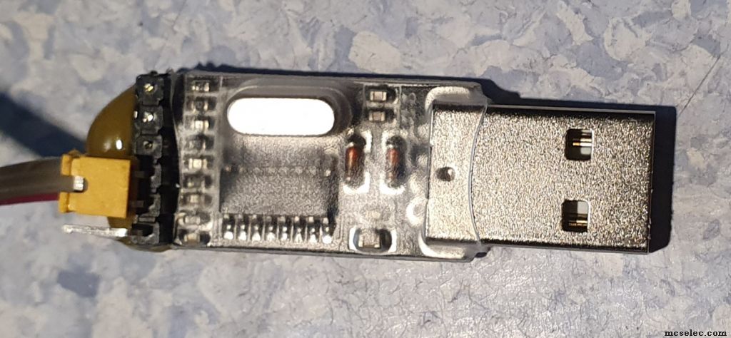
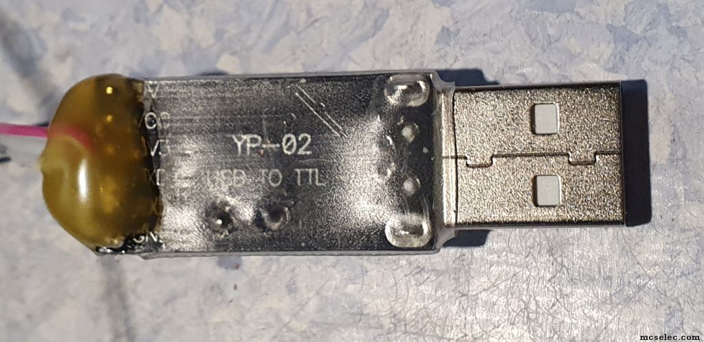
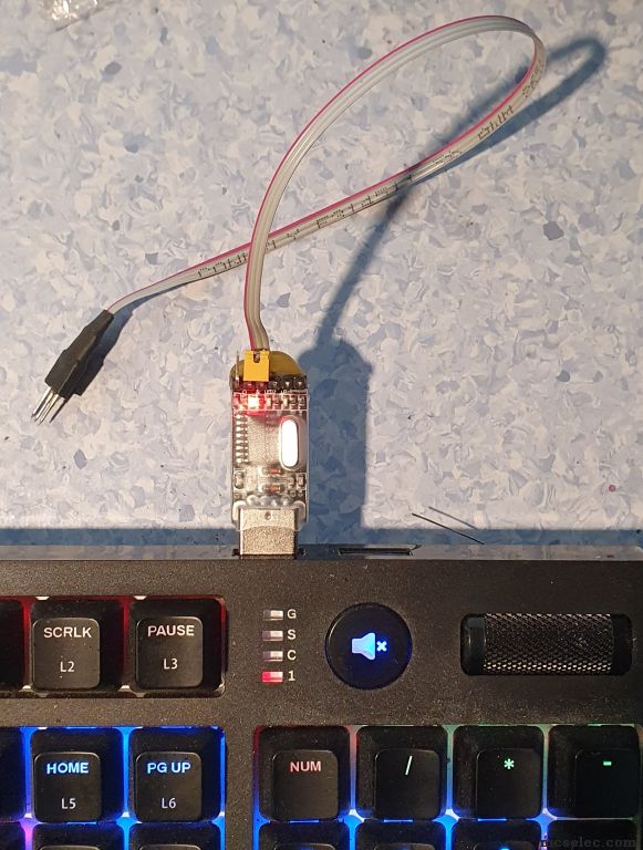
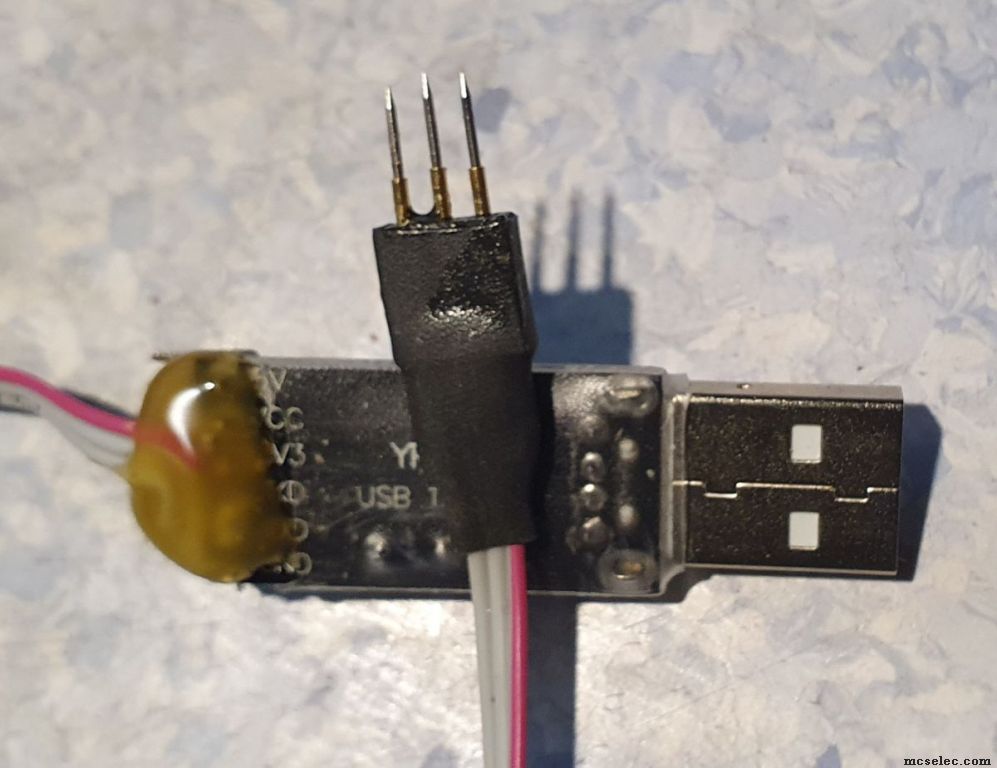
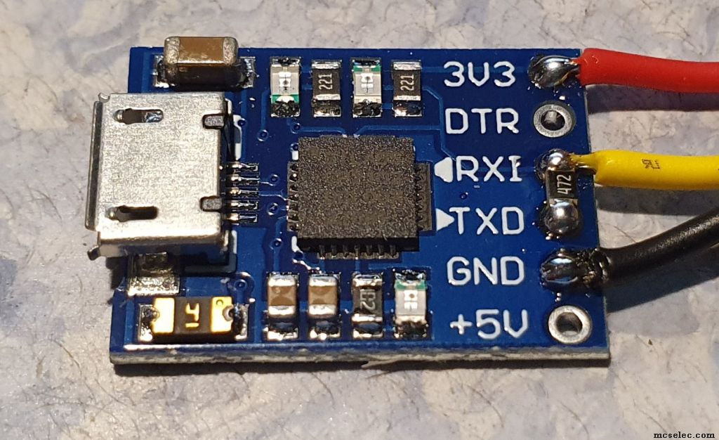
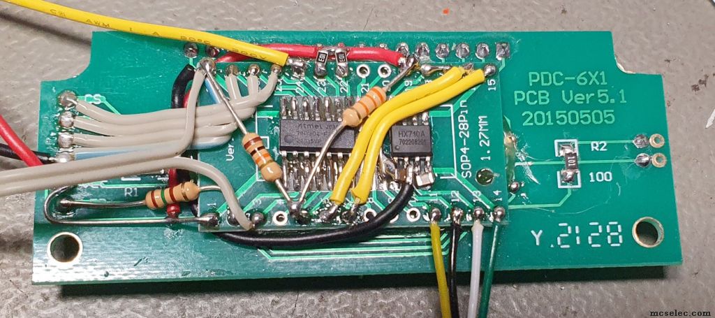
Hello guys. I just recently started with Xtiny family. Both CH340G and CP2102 work well for me. (Bascom AVR 2.0.8.5, WIN10 with all updates). Tested on Tiny3216 and Tiny804) Others I didn't test. Maybe this will help some beginner to bootstart his project.
If you really need a quick and dirt cheap UPDI programmer, you can use the USB to RS232 TTL adapter from our popular vendors. CH340G is the cheapest, about 1 with shipping. Since it already has a 1k5 resistor you can simply connect RX and TX together and you get UPDI. On CP2102 I added the 4k7 resistor and that's it. The only real downside of this programmer is it's speed. It is very slow, 8kB of code is loading ~20 seconds.
I'm planning to upgrade it to 12V HV-UPDI so I could use the pin for other purposes. If DTR could be used to trigger 12V pulse it would be great. I didn't check, if this is implemented yet (hint to Mark😉). I added some pics for reference, together with my dirty weighing scale prototype. I hope it heps somebody. All the best from me.
 |
|
| Back to top |
|
|
albertsm
Joined: 09 Apr 2004
Posts: 5921
Location: Holland
|
| Posted: Thu Apr 28, 2022 2:12 pm Post subject: |
|
|
Thanks for the info. All info helps, especial with pictures.
The 12V i like to implement too since you can get access to a locked chip this way.
DTR i use for switching between program mode and normal mode.
But of course that could be made selectable : using DTR or some other pin.
but how to generate the 12V ?
_________________
Mark |
|
| Back to top |
|
|
srecko
Joined: 05 Sep 2007
Posts: 23
Location: Dolenjske Toplice
|
| Posted: Thu Apr 28, 2022 11:39 pm Post subject: |
|
|
There are various ways to generate 12V, the most expensive one is using MAX622A charge pump. We can make a simple Dickson charge pump with a microcontroller, we can use boost converter (MT3608 or MT3540 for example) or even a small 12V battery, for example 27A or 23A. The pulse is only a trigger, it doesn't do anything else but change the pin to UPDI mode. I read somewhere, that it has to be at least Vdd * 2, so I assume some simple voltage comparator is on that pin.
The other thing is how to deliver this pulse to the UPDI pin without damaging the programmer. I saw one option with optocoupler, which wasn't so bad idea, since it also serves as a current limiter. It could be triggered by RTS for example and then simple CH330N chip could be used. BUT I'm a little bit worried about the fact, that it doesn't have external quartz and when I see any circuit communicating via RS232 without quartz, I get suspicious. So, if we use CH340G, then any of the flow control pins could be used, I guess... I will have to think about this.
Another thing is the speed. Why is it so slow? So much handshaking? Small packets and driver or hardware latency?
Also you mentioned programming mode and normal mode. Does UPDI programmer even have a normal mode?
I will make a small prototype with CH340G, voltage booster and optocoupler. Please, let me know which pin to use as a trigger. Then I can run some tests and maybe we'll make a good and cheap programmer, compatible with MCS UPDI programmer.
Best regards to all. |
|
| Back to top |
|
|
albertsm
Joined: 09 Apr 2004
Posts: 5921
Location: Holland
|
| Posted: Fri Apr 29, 2022 8:40 am Post subject: |
|
|
i am looking for a reliable and simple way to create 12V. And indeed it should not mess with the other connected hardware.
a battery is not a good solution. it get empty.
speed: when you check the protocol you can see there is a lot of communication. and there is only one direction. i do not get why they didnt use some SPI interface.
but newer chips can be programmer faster, i did not test that, it did not work out on xtiny, the platform i started with.
the info about the 12V pulse i can not find in all processor documents. so i also wonder if this applies to all updi chips. it is however described in pdf of the tiny816.
_________________
Mark |
|
| Back to top |
|
|
Paulvk
Joined: 28 Jul 2006
Posts: 1257
Location: SYDNEY
|
| Posted: Sat Apr 30, 2022 1:05 am Post subject: |
|
|
The max3232 charge pumps produce around 13v for the rs232 outputs and you get
two rs232 buffers.
Regards Paul |
|
| Back to top |
|
|
plouf
Joined: 19 Jan 2012
Posts: 78
Location: Athens,Greece

|
| Posted: Sat Apr 30, 2022 6:39 am Post subject: |
|
|
Why complicated additional circuit mist be used , and mot just an extrnal 12v psu plug to programmer with a simple transistor as a control of it ?
_________________
Christos |
|
| Back to top |
|
|
albertsm
Joined: 09 Apr 2004
Posts: 5921
Location: Holland
|
| Posted: Sat Apr 30, 2022 7:25 pm Post subject: |
|
|
of course everyone is free to use a 12V signal of his/her choice. personally i like to have all on one pcb but yes a simple DC jack with external 12V would do too.
_________________
Mark |
|
| Back to top |
|
|
|


