| View previous topic :: View next topic |
| Author |
Message |
enniom
Joined: 20 Oct 2009
Posts: 537
|
 Posted: Mon Apr 16, 2018 8:03 pm Post subject: USART as Master SPI - What is bit sequence? Posted: Mon Apr 16, 2018 8:03 pm Post subject: USART as Master SPI - What is bit sequence? |
 |
|
Hello,
I have a SPI device that works perfectly when SPI and SHIFTOUT code is used to Initialize and use the device. But, when I try to use USART in MSPI, I cannot get proper response.
| Code: | $regfile = "xm192a3udef.dat"
$hwstack = 80
$swstack = 80
$framesize = 80
$sim
$crystal = 32000000
Config Osc = Disabled , 32mhzosc = Enabled ' 32 MHz enabled
Config Sysclock = 32mhz , Prescalea = 1 , Prescalebc = 1_1
Waitms 2
Dim Test_byte As Byte
Test_byte = &B0001001
'==============================
'
'SPI Configuration
'
'==============================
Config Portd.4 = Output
Portd.4 = 1
Config Spid = Hard , Master = Yes , Mode = 0 , Data_order = Msb , Clockdiv = Clk2 , Ss = None
Spiinit ' Init SPI state and pins.
Spiout Test_byte , 1
'Based on Data_Order = MSB, the output bit sequence should be 1 0 0 1 0 0 0 0
'==============================
'
'SHIFTOUT Configuration
'
'==============================
Dev_sck Alias Porte.5
Dev_mosi Alias Porte.7
Config Dev_sck = Output
Config Dev_mosi = Output
Shiftout Dev_mosi , Dev_sck , Test_byte , 1
'Based on Option = 1, the output bit sequence should be 1 0 0 1 0 0 0 0
'==============================
'
'USART as Master SPI Configuration
'
'==============================
Config Com1 = 3200000 , Mode = Mspi , Parity = Disabled , Stopbits = 1 , Databits = 8
Printbin Test_byte
'QUESTION: is the output = 0 0 0 0 1 0 0 1 ??????
End
|
Questions:
1. is it correct that USART in Master SPI mode, the bits are shifted out LSB first? (At the moment, I do not know an easy way to find this out)
2. if it is true that the bits are shifted LSB first, is there a way to change it to MSB first?
Note: There is a byte order USARTxy_CTRLC.UDORD that will change the byte order for output Words ... but does not change the bit order.
Thanks
E
(BASCOM-AVR version : 2.0.8.1 ) |
|
| Back to top |
|
 |
EDC
Joined: 26 Mar 2014
Posts: 971

|
| Posted: Mon Apr 16, 2018 8:26 pm Post subject: |
|
|
Hello enniom I cant spent much time to the code analisis and tests but want to point for some thing.
Xmegas I know have UARTS in the SPI modes but then, if you want to this ports will be PIN-to-PIN then MOSI and SCK must be swapped in the SPI by port mapping.
It is better to design swapped those pins on the PCB because you can swap pins by mapping and have opportunity to use SPI or USART in SPI mode with DMA
So take in the account that pins in the SPI are not corresponding to the USART in SPI mode if PCB traces are not designed with think about REMAP`ing.
That was my 1 cent ahahaha  |
|
| Back to top |
|
|
enniom
Joined: 20 Oct 2009
Posts: 537
|
| Posted: Mon Apr 16, 2018 8:47 pm Post subject: |
|
|
Thanks EDC.
Yes I know about the change in XMEGA pins and that was taken into account (XCK,TX vs CLK,MOSI). This is not the problem.
I think, but I an not sure, the bit order in PRINTBIN is the problem.
[PS: I thought about reversing the bits for all commands/data to test this ... but that is too much work.]
E |
|
| Back to top |
|
|
MWS
Joined: 22 Aug 2009
Posts: 2262

|
| Posted: Mon Apr 16, 2018 9:16 pm Post subject: |
|
|
Used a while (5 years) ago UART in SPI mode for banging out data for WS2811, some code chunks:
| Code: | $regfile = "xm128a1def.dat"
'...
Const USART_TXEN = 3
Const USART_CMOD0 = 6
Const USART_CMOD1 = 7
Const USART_UCPHA = 1
Const USART_UDORD = 2
Const DMA_CH0TRNIF = 0
Const DMA_CH1TRNIF = 1
'...
'UART0 in SPI Mode, TXD --> PD3, XCK --> PD1 (unused)
Config PORTD.3 = Output ' set SPI TXD to output
USARTD0_BAUDCTRLA = 4 ' BSEL = (32MHz/(2*3.2MBaud))-1, 1/(1.25µs/4bit) = 3.2MBaud
USARTD0_BAUDCTRLB = 0 ' BSCALE = 0
USARTD0_CTRLA = 0
USARTD0_CTRLB = Bits(USART_TXEN) ' enable transmitter
USARTD0_CTRLC = Bits(USART_CMOD1 , USART_CMOD0) ' enable UART SPI-mode, MSB first, sample rising edge |
If I'd be you, I'd write a short program and I'd do a bit of a simulation, by checking USART_CMOD1..0 after Config Com1 ... you will find out in which mode SPI works.
Otherwise, set up the SPI-UART yourself like I did. |
|
| Back to top |
|
|
enniom
Joined: 20 Oct 2009
Posts: 537
|
| Posted: Mon Apr 16, 2018 9:49 pm Post subject: |
|
|
Thanks MWS.
I did see and used your earlier post as guidance.
I've checked all the registers and compared them to the datasheet and the command
| Code: |
Config Com1 = 3200000 , Mode = Mspi , Parity = Disabled , Stopbits = 1 , Databits = 8
|
does set the registers correctly - and as per your post. I think the problem is that the USART (PRINTBIN) shifts out the bits LSB first. The SPI, commands and data expects MSB first.
I've been thinking of using a "BIT Reverse" before PRINTBIN to see it that will work. Unfortunately to do this will be big job.
| Code: | !ldi r18,8
!ldi r17,0
!lds r16,{test_byte}
Rev_loop:
!lsr r16
!rol r17
!dec r18
!BRNE rev_loop
!sts {test_byte},r17
|
So before I begin this task, I was hoping to find out if there was a way of changing PRINTBIN to shift out MSB first??
E |
|
| Back to top |
|
|
EDC
Joined: 26 Mar 2014
Posts: 971
|
| Posted: Mon Apr 16, 2018 10:15 pm Post subject: |
|
|
| Printbin (even in Xmega.lib) use "_sendchar" at the end, but I dont see some place to move here. All USARTS sends LSB first (I`v read) and this indeed should can be reversed if ISP mode is used but I dont see this opportunity too |
|
| Back to top |
|
|
enniom
Joined: 20 Oct 2009
Posts: 537
|
| Posted: Mon Apr 16, 2018 10:30 pm Post subject: |
|
|
Thanks EDC and MWS.
I see that one option is to make a special USART output routine using $SERIALOUTPUT. From Help:
| Code: | $serialoutput = Myoutput
Do
Print "Hello"
Loop
End
Myoutput: 'perform the needed actions here the data arrives in R24 just set the output to PORTB
!outportb,r24
!ret
|
But now I would again need help with !ASM. I will happily do the hard work ... just need some hints to get started.
E |
|
| Back to top |
|
|
MWS
Joined: 22 Aug 2009
Posts: 2262
|
| Posted: Tue Apr 17, 2018 6:37 am Post subject: |
|
|
| enniom wrote: | | I think the problem is that the USART (PRINTBIN) shifts out the bits LSB first. |
Printbin() in its hardware version does not shift any bits, instead data bytes one by one are forwarded to the UART, which does the work of shifting things out.
The mentioned UART configuration bits decide about order of LSB/MSB first and not Printbin(). |
|
| Back to top |
|
|
enniom
Joined: 20 Oct 2009
Posts: 537
|
| Posted: Tue Apr 17, 2018 10:43 am Post subject: |
|
|
Hi MWS,
| Quote: | | UART configuration bits decide about order of LSB/MSB first |
I'm not able to find where this is set.
Also found this in data sheet. The byte order for Words is available in UDORD, but I cannot find the bit order?
| Quote: | 21.4.2 SPI Frame Formats
The serial frame in SPI mode is defined to be one character of 8 data bits.
The USART in Master SPI mode has two valid frame formats:
8-bit data with MSB first
8-bit data with LSB first
When a complete frame of 8 bits is transmitted, a new frame can directly follow it, or the communication
line returns to idle (high) state. |
E |
|
| Back to top |
|
|
enniom
Joined: 20 Oct 2009
Posts: 537
|
| Posted: Tue Apr 17, 2018 2:50 pm Post subject: |
|
|
Is it possible that UDORD is intended to be the bit order?
EDIT: Confirmed that USARTxy_CTRLC.UDORD does change the Byte order of a Word when PRINTBIN sends out a Word {Var}; but has no effect on the Bit Order. |
|
| Back to top |
|
|
enniom
Joined: 20 Oct 2009
Posts: 537
|
| Posted: Tue Apr 17, 2018 5:20 pm Post subject: |
|
|
.
UPDATE:
Tried using Synchroneous Mode and all works properly! SPI Mode does not.
| Code: | Config Com6 = 256000 , Mode = Synchroneous , Parity = None , Stopbits = 1 , Databits = 8
'Config Com6 = 256000 , Mode = Spi , Parity = None , Stopbits = 1 , Databits = 8
Open "COM6:" For Binary As #1
|
The major difference in these is the available maximum speed.
E |
|
| Back to top |
|
|
MWS
Joined: 22 Aug 2009
Posts: 2262
|
| Posted: Tue Apr 17, 2018 5:37 pm Post subject: |
|
|
| enniom wrote: | | I'm not able to find where this is set. |
In my code - however for a different processor - I've defined the bit-names myself, if you resolve my constant definitions you get: USARTD0_CTRLC.7 and 6.
I did not check whether bit-names are equal for xm192a3u, but thought you will look up my used xm128a1d and draw the comparison. |
|
| Back to top |
|
|
enniom
Joined: 20 Oct 2009
Posts: 537
|
| Posted: Thu Apr 19, 2018 12:54 am Post subject: |
|
|
Hi MWS,
Sorry for not replying earlier.

I'm reasonably certain that all Series A (1 or 3) XMega have the same registers for the USART as Master SPI. The excerpt from the data sheet shows only UDORD as the Reg.Bit that allows for LSB or MSB shifting. I have confirmed that it works.
I think the problem I'm having is related to matching the Config Baud Rate with Register Values. When a Byte is transmitted out, there is some type of problem that I need to understand. Don't know if I'm creating the problem, or if it is Bascom.

E |
|
| Back to top |
|
|
AdrianJ
Joined: 16 Jan 2006
Posts: 2483
Location: Queensland

|
| Posted: Thu Apr 19, 2018 5:42 am Post subject: |
|
|
SPI mode should not be affected by baud rate, its a synchronous system ( clock + data ). Unless of course the target slave cant keep up with the clock rate you set.
_________________
Adrian Jansen
Computer language is a framework for creativity |
|
| Back to top |
|
|
enniom
Joined: 20 Oct 2009
Posts: 537
|
| Posted: Fri Apr 20, 2018 9:42 pm Post subject: |
|
|
[SOLVED]
Thank-you MWS and AdrianJ.
After reading the XMega A Manual at least 27 times, I found a hint here:
| Quote: | 21.11 USART SPI vs. SPI
When the USART is set in master SPI mode, configuration and use are in some cases different from those of the
standalone SPI module. In addition, the following differences exist:
1. The USART transmitter in master SPI mode includes buffering, but the SPI module has no transmit buffer
2. The USART receiver in master SPI mode includes an additional buffer level
3. The USART in master SPI mode does not include the SPI write collision feature
4. The USART in master SPI mode does not include the SPI double speed mode feature, but this can be achieved by configuring the baud rate generator accordingly
5. Interrupt timing is not compatible
6. Pin control differs due to the master-only operation of the USART in SPI master mode. |
| Quote: | 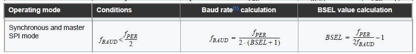 |
This code works properly:
| Code: | Lcd_sck Alias Porte.1
Lcd_rx Alias Porte.2
Lcd_mosi Alias Porte.3
Config Lcd_sck = Output
Config Lcd_mosi = Output
Config Lcd_rx = Input
Config Com5 = 8000000 , Mode = Mspi , Parity = Disabled , Stopbits = 1 , Databits = 8
Open "COM5:" For Binary As #1
'.....
Lcd_cs = 0 : Lcd_dc = 0
Printbin #1 , Command
Waitus 1 '<<<<<<<<< Without this short wait, the transmission FAILS!!
Lcd_cs = 1
'........
Lcd_cs = 0 : Lcd_dc = 1
Printbin #1 , Da_ta
Waitus 1 '<<<<<<<<<<
Lcd_cs = 1
|
Findings during this development:
1. Without a short delay after transmitting data via MSPI, the transmission fails. It may be related to the buffer or collision (items 1 & 3 above in the A Manual).
2. The Config MSPI statement does not calculate BSEL correctly (except when BSEL = 0 or 1).
3. Even though the manual states that Fbaud < Fper / 2, it seems MSPI works with BSEL = 0 and Fbaud = Fper / 2.
4. The Bascom Simulator Variables Display Screen does not recognize USARTxy_BAUDCTRLA / B as variables - but the register values are simulated.
5. If the Bootloader includes: | Code: | Config Intvectorselection = Enabled
On [Interrupt] [ISR]
Enable [Interrupt], Lo/Med/Hi
Enable Interrupts |
Once control moves from the Bootloader to the Main program area, the active and the global interrupts CANNOT be disabled - even if Config Intvectorselection = Disabled is used. It seems as if active interrupts need to be Disabled before leaving the Bootloader area???
[Question: Is there a place the short wait can be inserted (MCS.LIB?) after Printbin shifts out the last bit??]
E
Last edited by enniom on Sat Apr 21, 2018 1:07 pm; edited 1 time in total |
|
| Back to top |
|
|
|


