| View previous topic :: View next topic |
| Author |
Message |
MichaelB.
Joined: 04 May 2017
Posts: 58

|
 Posted: Wed Jul 12, 2017 11:10 am Post subject: Bascom Spi Newbie Problem Posted: Wed Jul 12, 2017 11:10 am Post subject: Bascom Spi Newbie Problem |
 |
|
Hi again, for a newbie Problem, and need a Specialist for SPI.
This time i try me on the SPI comunication between a Atmega32 and a SCA100T-D02 Anglesensor.
I make some Comments in the Code for you that will may help.
First, i had Create and send a 8 bit register code to the Anglesensor, to say that i will only read the 11 bit " Y " Values from the Sensor.
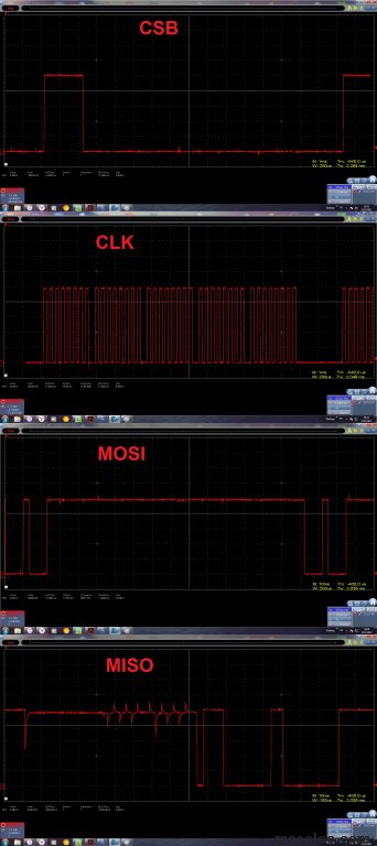
After that, i send two 8 bit packages to Shift it in the sensor, and the Sensor answers on the MISO line with the Y values.
I checked that with my "PeakTech 1350" Pen-Type Oscilloscpoe.
The "Y" Values on the MISO line is changing as Expected when tilt the Sensor.
BUT. Nothing more happens. My expectaion is that the MISO data "LoadY" is convert it into "Wert1"
The Zero Angle Position is "10000000000" witch is 1024, and in my Code it shall show me on my 7Segments a " 0 " on my Breadbord.
But it shows nothing, what do i miss here. Can anyone Help me in this case?
Best Regards
Michael
(BASCOM-AVR version : 2.0.7.8 ) |
|
| Back to top |
|
 |
MWS
Joined: 22 Aug 2009
Posts: 2335

|
| Posted: Wed Jul 12, 2017 6:36 pm Post subject: |
|
|
First: you can not be serious to post code as bitmap.
In case the uC is the master, SPI communication depends on shifting bits out via MOSI, master out slave in, and getting bits in via MISO, master in slave out.
The visible bitmap-part of your code uses nowhere commands to get data like SPIIN, SPIMOVE, there's only SPIOUT, you only talk but you do not listen.
Do you expect the requested bits are somehow magically transferred into the uC?
You have to cut down the controllers case at least one mm to make that magic work, i.e. let it out LOL |
|
| Back to top |
|
|
albertsm
Joined: 09 Apr 2004
Posts: 6198
Location: Holland
|
| Posted: Wed Jul 12, 2017 9:20 pm Post subject: |
|
|
Michael, some pictures say more than 1000 words but in order to give help, you should post code, and please embed them with the CODE tags.
This way we can copy and past the code and check it.
Also, when using some chip, give a link to the data sheet PDF so we do not need to search for the data sheet.
_________________
Mark |
|
| Back to top |
|
|
MichaelB.
Joined: 04 May 2017
Posts: 58
|
| Posted: Thu Jul 13, 2017 12:42 pm Post subject: |
|
|
Oh sure. Here is the PDF and the Code.
http://www.produktinfo.conrad.com/datenblaetter/400000-424999/406067-da-01-en-NEIGUNGSSENSOR_SCA100T_D02.pdf
| Code: |
$regfile = "m32def.dat"
$crystal = 16000000
$framesize = 256
$swstack = 256
$hwstack = 256
Config Porta.0 = Output
Config Porta.1 = Output
Config Porta.2 = Output
Config Porta.3 = Output
Config Porta.4 = Output
Config Porta.5 = Output
Config Porta.6 = Output
Config Porta.7 = Output
Config Portb.0 = Output 'LED
Config Portb.1 = Output
Config Portb.2 = Output
Config Portb.3 = Output
Config Portc.0 = Output 'LED
Config Portc.1 = Output
Config Portc.6 = Output
Config Portc.7 = Output
Config Portd.4 = Output 'LED
Config Portd.5 = Output
'Links
LEDLa alias PortB.0 ' 1er
LEDLb alias portB.1
LEDLc alias PortB.2
LEDLd alias PortB.3
LEDLe alias Porta.0
LEDLf alias Porta.1
LEDLg alias Porta.2
LEDL2b alias Porta.6 '10er
LEDL2c alias Porta.7
'Rechts
LEDRa alias Portc.0
LEDRb alias Portc.1 '1er
LEDRc alias Porta.3
LEDRd alias Portc.6
LEDRe alias Portc.7
LEDRf alias Porta.4
LEDRg alias Porta.5
LEDR2b alias Portd.5 '10er
LEDR2c alias Portd.4
Config Portb.4 = Output 'Chipselect
Portb.4 = 1 'Chipselect = off
Dim LoadY as Word '11 bit Slave Value Output (MISO)
Dim LoadYL as Byte at LoadY Overlay
Dim LoadYH as Byte at LoadY + 1 Overlay
Dim WertY as Byte
WertY = &B00010001 ' Y slave Register code
Dim Wert1 as Word
Config SPI = Hard , Interrupt = off , Master = Yes , Data_order = Msb , Polarity = Low , Phase = 0 , Clockrate = 128 , Noss = 1 ' mega32 with 16mhz
Spiinit
Cls
Do
Portb.4 = 0 'chip select on
Spiout WertY , 1 ' Send "Y" Register code
Spiout LoadYH , 1 'Send first 8 Bit of a 16 bit Word
Spiout LoadYL , 1 ' Send second 8 Bit of a 16 bit Word
Portb.4 = 1 'chip select off
Wert1 = LoadY
' Right
If Wert1 = 1009 then ' 15
LEDRa = 1
LEDRf = 1
LEDRg = 1
LEDRc = 1
LEDRd = 1
LEDR2b = 1
LEDR2c = 1
waitms 5000
LEDRa = 0
LEDRf = 0
LEDRg = 0
LEDRc = 0
LEDRd = 0
LEDR2b = 0
LEDR2c = 0
End if
If Wert1 = 1010 then ' 14
LEDRf = 1
LEDRg = 1
LEDRb = 1
LEDRc = 1
LEDR2b = 1
LEDR2c = 1
waitms 5000
LEDRf = 0
LEDRg = 0
LEDRb = 0
LEDRc = 0
LEDR2b = 0
LEDR2c = 0
End if
If Wert1 = 1011 then ' 13
LEDRa = 1
LEDRb = 1
LEDRg = 1
LEDRc = 1
LEDRd = 1
LEDR2b = 1
LEDR2c = 1
waitms 5000
LEDRa = 0
LEDRb = 0
LEDRg = 0
LEDRc = 0
LEDRd = 0
LEDR2b = 0
LEDR2c = 0
End if
If Wert1 = 1012 then ' 12
LEDRa = 1
LEDRb = 1
LEDRg = 1
LEDRe = 1
LEDRd = 1
LEDR2b = 1
LEDR2c = 1
waitms 5000
LEDRa = 0
LEDRb = 0
LEDRg = 0
LEDRe = 0
LEDRd = 0
LEDR2b = 0
LEDR2c = 0
End if
If Wert1 = 1013 then ' 11
LEDRb = 1
LEDRc = 1
LEDR2b = 1
LEDR2c = 1
waitms 5000
LEDRb = 0
LEDRc = 0
LEDR2b = 0
LEDR2c = 0
End if
If Wert1 = 1014 then ' 10
LEDRa = 1
LEDRb = 1
LEDRc = 1
LEDRd = 1
LEDRe = 1
LEDRf = 1
LEDR2b = 1
LEDR2c = 1
waitms 5000
LEDRa = 0
LEDRb = 0
LEDRc = 0
LEDRd = 0
LEDRe = 0
LEDRf = 0
LEDR2b = 0
LEDR2c = 0
End if
If Wert1 = 1015 then ' 9
LEDRa = 1
LEDRb = 1
LEDRc = 1
LEDRd = 1
LEDRg = 1
LEDRf = 1
waitms 5000
LEDRa = 0
LEDRb = 0
LEDRc = 0
LEDRd = 0
LEDRg = 0
LEDRf = 0
End if
If Wert1 = 1016 then ' 8
LEDRa = 1
LEDRb = 1
LEDRc = 1
LEDRd = 1
LEDRe = 1
LEDRf = 1
LEDRg = 1
waitms 5000
LEDRa = 0
LEDRb = 0
LEDRc = 0
LEDRd = 0
LEDRe = 0
LEDRf = 0
LEDRg = 0
End if
If Wert1 = 1017 then ' 7
LEDRa = 1
LEDRb = 1
LEDRc = 1
waitms 5000
LEDRa = 0
LEDRb = 0
LEDRc = 0
End if
If Wert1 = 1018 then ' 6
LEDRa = 1
LEDRf = 1
LEDRg = 1
LEDRe = 1
LEDRd = 1
LEDRc = 1
waitms 5000
LEDRa = 0
LEDRf = 0
LEDRg = 0
LEDRe = 0
LEDRd = 0
LEDRc = 0
End if
If Wert1 = 1019 then ' 5
LEDRa = 1
LEDRf = 1
LEDRg = 1
LEDRc = 1
LEDRd = 1
waitms 5000
LEDRa = 0
LEDRf = 0
LEDRg = 0
LEDRc = 0
LEDRd = 0
End if
If Wert1 = 1020 then ' 4
LEDRf = 1
LEDRg = 1
LEDRb = 1
LEDRc = 1
waitms 5000
LEDRf = 0
LEDRg = 0
LEDRb = 0
LEDRc = 0
End if
If Wert1 = 1021 then ' 3
LEDRa = 1
LEDRb = 1
LEDRg = 1
LEDRc = 1
LEDRd = 1
waitms 5000
LEDRa = 0
LEDRb = 0
LEDRg = 0
LEDRc = 0
LEDRd = 0
End if
If Wert1 = 1022 then ' 2
LEDRb = 1
LEDRa = 1
LEDRg = 1
LEDRe = 1
LEDRd = 1
waitms 5000
LEDRb = 0
LEDRa = 0
LEDRg = 0
LEDRe = 0
LEDRd = 0
End if
If Wert1 = 1023 then ' 1
LEDRb = 1
LEDRc = 1
waitms 5000
LEDRb = 0
LEDRc = 0
End if
If Wert1 = 1024 then ' 0
LEDRa = 1
LEDRb = 1
LEDRc = 1
LEDRd = 1
LEDRe = 1
LEDRf = 1
LEDLa = 1
LEDLb = 1
LEDLc = 1
LEDLd = 1
LEDLe = 1
LEDLf = 1
waitms 5000
LEDRa = 0
LEDRb = 0
LEDRc = 0
LEDRd = 0
LEDRe = 0
LEDRf = 0
LEDLa = 0
LEDLb = 0
LEDLc = 0
LEDLd = 0
LEDLe = 0
LEDLf = 0
End if
'Left
If Wert1 = 1025 then '1
LEDLb = 1
LEDLc = 1
waitms 5000
LEDLb = 0
LEDLc = 0
End if
If Wert1 = 1026 then '2
LEDLb = 1
LEDLg = 1
LEDLa = 1
LEDLe = 1
LEDLd = 1
waitms 5000
LEDLb = 0
LEDLg = 0
LEDLa = 0
LEDLe = 0
LEDLd = 0
End If
If Wert1 = 1027 then '3
LEDLa = 1
LEDLb = 1
LEDLg = 1
LEDLc = 1
LEDLd = 1
waitms 5000
LEDLa = 0
LEDLb = 0
LEDLg = 0
LEDLc = 0
LEDLd = 0
End If
If Wert1 = 1028 then '4
LEDLf = 1
LEDLg = 1
LEDLb = 1
LEDLc = 1
waitms 5000
LEDLf = 0
LEDLg = 0
LEDLb = 0
LEDLc = 0
End if
If Wert1 = 1029 then '5
LEDLa = 1
LEDLf = 1
LEDLg = 1
LEDLc = 1
LEDLd = 1
waitms 5000
LEDLa = 0
LEDLf = 0
LEDLg = 0
LEDLc = 0
LEDLd = 0
End if
If Wert1 = 1030 then '6
LEDLa = 1
LEDLf = 1
LEDLg = 1
LEDLc = 1
LEDLd = 1
waitms 5000
LEDLa = 0
LEDLf = 0
LEDLg = 0
LEDLc = 0
LEDLd = 0
End if
If Wert1 = 1031 then '7
LEDLa = 1
LEDLb = 1
LEDLc = 1
waitms 5000
LEDLa = 0
LEDLb = 0
LEDLc = 0
End if
If Wert1 = 1032 then '8
LEDLa = 1
LEDLb = 1
LEDLc = 1
LEDLd = 1
LEDLe = 1
LEDLf = 1
LEDLg = 1
waitms 5000
LEDLa = 0
LEDLb = 0
LEDLc = 0
LEDLd = 0
LEDLe = 0
LEDLf = 0
LEDLg = 0
End if
If Wert1 = 1033 then '9
LEDLa = 1
LEDLb = 1
LEDLc = 1
LEDLd = 1
LEDLf = 1
LEDLg = 1
waitms 5000
LEDLa = 0
LEDLb = 0
LEDLc = 0
LEDLd = 0
LEDLf = 0
LEDLg = 0
End if
If Wert1 = 1034 then '10
LEDLa = 1
LEDLb = 1
LEDLc = 1
LEDLe = 1
LEDLf = 1
LEDLd = 1
LEDL2b = 1
LEDL2c = 1
waitms 5000
LEDLa = 0
LEDLb = 0
LEDLc = 0
LEDLe = 0
LEDLf = 0
LEDLd = 0
LEDL2b = 0
LEDL2c = 0
End if
If Wert1 = 1035 then '11
LEDLb = 1
LEDLc = 1
LEDL2b = 1
LEDL2c = 1
waitms 5000
LEDLb = 0
LEDLc = 0
LEDL2b = 0
LEDL2c = 0
End if
If Wert1 = 1036 then '12
LEDLa = 1
LEDLb = 1
LEDLg = 1
LEDLe = 1
LEDLd = 1
LEDL2b = 1
LEDL2c = 1
waitms 5000
LEDLa = 0
LEDLb = 0
LEDLg = 0
LEDLe = 0
LEDLd = 0
LEDL2b = 0
LEDL2c = 0
End if
If Wert1 = 1037 then '13
LEDLa = 1
LEDLb = 1
LEDLc = 1
LEDLd = 1
LEDLg = 1
LEDL2b = 1
LEDL2c = 1
waitms 5000
LEDLa = 0
LEDLb = 0
LEDLc = 0
LEDLd = 0
LEDLg = 0
LEDL2b = 0
LEDL2c = 0
End if
If Wert1 = 1038 then '14
LEDLf = 1
LEDLg = 1
LEDLb = 1
LEDLc = 1
LEDL2b = 1
LEDL2c = 1
waitms 5000
LEDLf = 0
LEDLg = 0
LEDLb = 0
LEDLc = 0
LEDL2b = 0
LEDL2c = 0
End if
If Wert1 = 1039 then '15
LEDLa = 1
LEDLf = 1
LEDLg = 1
LEDLc = 1
LEDLd = 1
LEDL2b = 1
LEDL2c = 1
waitms 5000
LEDLa = 0
LEDLf = 0
LEDLg = 0
LEDLc = 0
LEDLd = 0
LEDL2b = 0
LEDL2c = 0
End if
Loop
End |
|
|
| Back to top |
|
|
kimmi
Joined: 24 Feb 2006
Posts: 1922
Location: Denmark

|
| Posted: Thu Jul 13, 2017 4:05 pm Post subject: |
|
|
why do you have "Cls" in your code its for lcd !!!!
and how did you connect 7 segment the :
| Code: | LEDL2b alias Porta.6 '10er
LEDL2c alias Porta.7
LEDR2b alias Portd.5 '10er
LEDR2c alias Portd.4
|
is not clear to me what it do
_________________
/ Kim |
|
| Back to top |
|
|
MichaelB.
Joined: 04 May 2017
Posts: 58
|
| Posted: Thu Jul 13, 2017 5:39 pm Post subject: |
|
|
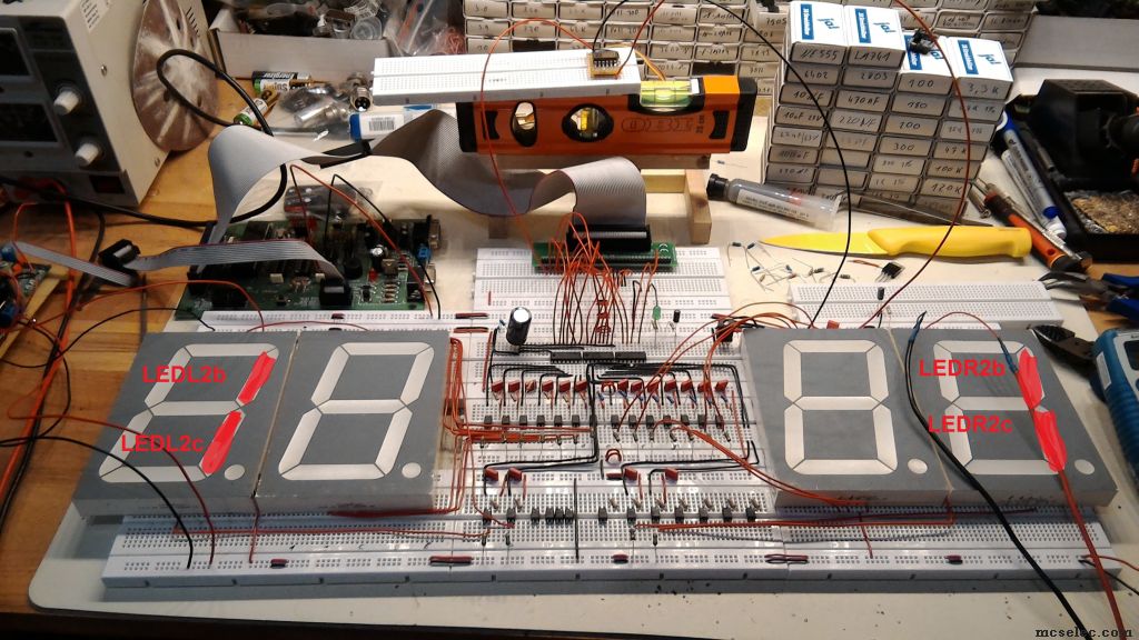
Maybe my mess will help you ^^
 |
|
| Back to top |
|
|
MWS
Joined: 22 Aug 2009
Posts: 2335
|
| Posted: Thu Jul 13, 2017 6:48 pm Post subject: |
|
|
Hmm, what you're discussing about?
Led-pins?
Why?
It may be funny to discuss such things, but this does not solve anything. Makes no sense.
I wrote it already: if one wants to get data, one needs to fetch them, in this case from MOSI.
And this has to be done by clocking 11 bits in, the schema on page 12 shows exactly how to do it.
As it is described there, 11 bits need to be clocked in.
It is not clear what happens, if 16 bits are clocked in, in case the chip locks up while trying to clock 16 bit, then reading data can not be done with hardware SPI, which works on multiples of its register width of 8 bits.
Then it needs to be done with some simple code, however watching the TO's uninspired code-snake, I'm not sure if he can handle it.
But in case he's lucky, it won't matter whether clocking 11 or 16 bits in, clocking 2 bytes in by SPIIN() will be enough then, the 5 bits with invalid data can be removed either by shifting or masking. |
|
| Back to top |
|
|
albertsm
Joined: 09 Apr 2004
Posts: 6198
Location: Holland
|
| Posted: Thu Jul 13, 2017 8:09 pm Post subject: |
|
|
TS mentioned he is a newbie with bascom so it will be good to show how to do it better.
But you are right : the LED stuff complicates and distracts from the actual problem.
When having a problem it is good practice to isolate it. this means : create a short as possible sample that still works (or should work). This is also true for the hardware.
For debugging you can use a 7-segment display but i would recommend to use the UART/serial port. that way you can simply use : PRINT "somevalue " ; wert
The help shows how to connect the TX pin to a max232 for connection to the PC.
spimove() might indeed work but a simple loop where you create the signals can do the job too. try to get a proper debug output first. then try hw SPI and if that does not work you can try the 'make your own signals' solution.
_________________
Mark |
|
| Back to top |
|
|
kimmi
Joined: 24 Feb 2006
Posts: 1922
Location: Denmark
|
| Posted: Thu Jul 13, 2017 11:55 pm Post subject: |
|
|
| MWS wrote: | Hmm, what you're discussing about?
Led-pins?
Why?
It may be funny to discuss such things, but this does not solve anything. Makes no sense.
|
I know you did not see why I ask
but the long setup of the 7 segment's
can be made more simple with a lookup table
| MWS wrote: |
But in case he's lucky, it won't matter whether clocking 11 or 16 bits in, clocking 2 bytes in by SPIIN() will be enough then, the 5 bits with invalid data can be removed either by shifting or masking.
|
when it's so simple why don't you just tell him that : Loadyh & Loadyl must be Spiin
| Code: | Portb.4 = 0 'chip select on
Spiout WertY , 1 ' Send "Y" Register code
Spiin Loadyh , 1 'Get first 3 Bit of a 11 bit Word
Spiin Loadyl , 1 ' Get second 8 Bit of a 11 bit Word
Portb.4 = 1 'chip select off
|
We can all make a simple write error but never see it (blind from 1000 times code read)
@Addon file for a simpler 7 segment
_________________
/ Kim |
|
| Back to top |
|
|
MichaelB.
Joined: 04 May 2017
Posts: 58
|
| Posted: Fri Jul 14, 2017 7:31 am Post subject: |
|
|
I tryed also this version:
| Code: | Portb.4 = 0
Spiout WertY , 1
Spiout LoadYH , 1
Spiout LoadYL , 1
Spiin LoadYH ,1
Spiin LoadYL , 1
Portb.4 = 1 |
This make more sense to me, but sill nothing on the Led´s. I tryed to Fuse the Spiin bytes together and Shifted 5 bits to the Right, i make it complicate as hell, and confused me more.
In my Code without Spiin, i thought it must work because its a shift register. That data that comes out of the Master MOSI Line, comes automaticly in the Master MISO Line, and i thought Spiin is only for the Slave Devices.
Next Week i can try it only with Spiin.
And sorry about the Confusing Breadboard Picture. |
|
| Back to top |
|
|
MWS
Joined: 22 Aug 2009
Posts: 2335
|
| Posted: Fri Jul 14, 2017 10:10 am Post subject: |
|
|
| kimmi wrote: | | I know you did not see why I ask |
I simply did not bother to think about, as the main problem is so obvious, that it needs to fixed first, before making any cosmetic changes.
The code for the display is a mess, agreed, but has the potential to work. But that does not matter, if no data coming in, which is the primary goal.
After the main issue is fixed, you'll have a point and I will agree, that this messy display-routine urgently needs a fix. |
|
| Back to top |
|
|
benoit
Joined: 24 Jul 2007
Posts: 177

|
| Posted: Fri Jul 14, 2017 12:31 pm Post subject: |
|
|
HI
Just:
THE STATUT FOR PORT B5 AND PORT B6 ARE NOT DEFINED AS INPUT OR OUTPUT .
I don t know if it can change something.
thank you to tell
 |
|
| Back to top |
|
|
MWS
Joined: 22 Aug 2009
Posts: 2335
|
| Posted: Fri Jul 14, 2017 1:02 pm Post subject: |
|
|
| MichaelB. wrote: | | In my Code without Spiin, i thought it must work because its a shift register. That data that comes out of the Master MOSI Line, comes automaticly in the Master MISO Line |
No, there's no magic reading of MISO.
| Quote: | | and i thought Spiin is only for the Slave Devices. |
The controller is configured as SPI-master, your sensor is the slave.
If you check page 12 of the datasheet, you'll notice 8 bits, the command (watch SCK, 8-times going from low to high) is clocked out and after eleven bits are clocked in, so you can try to SPIOUT command-byte and after SPIIN result-word.
But, and I mentioned that in my post before, it may confuse the sensor, as it expects 11 clocks to shift out its data, while actually the SCK-pin is driven with 16 clocks from the µC.
Watching the page 12 diagram, CSB (the enable-pin of the sensor) goes low first, then the command byte is clocked to the sensor, after the result is clocked from the sensor, the MOSI-line is crisscrossed meanwhile, as the MOSI level is ignored, while getting the result via MISO.
On the panoramic view of the electronic one can barely notice 4 wires running to the sensor, that have to be: plus, ground, MOSI, MISO.
The fifth wire for CSB is not visible, so it can be assumed, that CSB is not connected or constantly held low, means the sensor is always addressed.
It may happen then, that the superfluous 5 clocks irritate the sensor and are taken as part of a next command-byte, this way screwing all further reads, even if the first one actually gave a good result. Then you need some sort of custom soft-SPI, which exactly behaves as the controller expects it.
Because of this, it is highly recommendable to connect and drive CSB, as this explicitly tells the sensor the start of the sequence, which may also act as sensor-reset and would thus allow to clock even 16 bits, because it removes the irritation of the 5 bits too much. |
|
| Back to top |
|
|
MWS
Joined: 22 Aug 2009
Posts: 2335
|
| Posted: Fri Jul 14, 2017 1:18 pm Post subject: |
|
|
| benoit wrote: | | THE STATUT FOR PORT B5 AND PORT B6 ARE NOT DEFINED AS INPUT OR OUTPUT |
Why do you shout out?
SPIINIT takes care of setting the portpins, you just need to read the help. |
|
| Back to top |
|
|
MichaelB.
Joined: 04 May 2017
Posts: 58
|
|
| Back to top |
|
|
|
|
You cannot post new topics in this forum
You cannot reply to topics in this forum
You cannot edit your posts in this forum
You cannot delete your posts in this forum
You cannot vote in polls in this forum
You cannot attach files in this forum
You cannot download files in this forum
|
|