| View previous topic :: View next topic |
| Author |
Message |
Paulvk
Joined: 28 Jul 2006
Posts: 1257
Location: SYDNEY

|
 Posted: Wed Oct 26, 2016 9:28 am Post subject: Mega 1284P smt board takes Arduino shields Posted: Wed Oct 26, 2016 9:28 am Post subject: Mega 1284P smt board takes Arduino shields |
 |
|
For those like myself that wanted to use the wiznet shields and find that the Arduino boards do not have enough ram or are large as in the M2560
I have made a board that takes the surface mount versions of the mega avrs in 44pin so you have a number of choices of which chip to use.
It has:
Provision for the arduino shields
ISP connection
5 pin switching regulator so up to 7amps fixed or variable depending which one you use
MAX3232 for two serial ports
I2C resistors
I2C Real time clock RX-8025 this one is factory calibrated & provision for battery
Extra headers so all the ports can be used
Board is 70mm x 68mm in size double sided and cost me $4.50 AU with 3 day shipping each to have 10 made in china
It is not difficult to solder by hand
Made with Kicad so you can modify it if you want
The gerber files needed to have it made are in the zip file
When I get more time I will add more information to the silk screen
Will also add the code for the real time clock
Regards Paul |
|
| Back to top |
|
 |
Duval JP
Joined: 22 Jun 2004
Posts: 1198
Location: France

|
| Posted: Wed Oct 26, 2016 3:33 pm Post subject: |
|
|
Hi Paul,
would you like post a photo please ?

jp |
|
| Back to top |
|
|
Evert :-)
Joined: 18 Feb 2005
Posts: 2165

|
| Posted: Wed Oct 26, 2016 3:57 pm Post subject: |
|
|
Hi Paul,
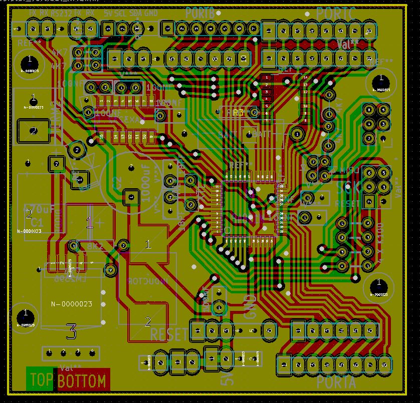
Thanks for sharing. Nice design as far I can judge from the pcb.
I'm missing the schematic or the bom list. Hard to buy and place components this way
@jp, not really a picture but screenshot from kicad.
 [/img] [/img]
_________________
www.evertdekker.com Bascom code vault |
|
| Back to top |
|
|
Paulvk
Joined: 28 Jul 2006
Posts: 1257
Location: SYDNEY
|
| Posted: Thu Oct 27, 2016 8:52 am Post subject: |
|
|
Hello JP & Evert
I will have to make a list of components
as there is no circuit diagram
I have made circuit boards long before CAD was invented
so they are built in my head but if I finish the silk screens
then you will have that on the board fairly simple to follow.
I also have a board with a 40pin dip for an avr and for a ICL7109 ADC
this is an old chip but still in production it has a + & - 5v supply
so it can measure +/- 200mv or +/- 2V great for battery current meters or negative voltages.
If there is interest in it I will put a blog up on its construction & programs
Regards Paul |
|
| Back to top |
|
|
Paulvk
Joined: 28 Jul 2006
Posts: 1257
Location: SYDNEY
|
| Posted: Sat Oct 29, 2016 7:25 am Post subject: |
|
|
Ok Parts list
switch mode regulator LM2576, LM2596, LM2678, LM5576 5 Pin regulators the one that suits your purpose
Note there is provision to use a variable regulator and also a 3.3v can be used for 5v by using a 1500 resistor on the sense pin
surface mount inductor to suit above
capacitor for regulator refer to above regulators (I use 1000uF 6.3v for all as I have lots of them)
3 amp schottky surface mount diode for regulator
3 amp diode with leads for power connection reverse protection
two pin screw terminal for unregulated DC supply
2 x 4700 ohms (I2C pull ups)
set of sockets for Arduino sheild
MAX3232 in 16 pin SOIC
RX8025 I2C real time clock
Atmega in 44Pin TQFP (a number of choices here)
2 x 3 6 pin male header vertical (Arduino shield MISO, MOSI, CLK , Reset and +/- )
2 x 3 6 pin male header right angle for ISP programmer
4off 8 pin headers single row for ports
3off 3 pin headers single row for RS232 and I2C
2 diodes for battery back up of clock chip IN4184 or similar
7 x 100nF caps for MAX3232 and bypass
Battery for clock (your choice of 3v)
You can see there are a number of options to the way the board is built
you may not want the screw terminals or the switch mode regulator
there is provision for +5V or +3V to be fed to the board or from the board.
By using the Wiznet shields you get the SD card socket and TCPIP with a bunch of flashing leds 
Now to find time to tidy up silk screen of components
Note the surface mount chips are not that hard to solder by hand using the "Solder Wick technique "
I use a pencil with a small bit of double sided tape on the end to hold the IC and position it on the board while soldering
Regards Paul |
|
| Back to top |
|
|
|


