| View previous topic :: View next topic |
| Author |
Message |
Rick-S
Joined: 08 Jan 2009
Posts: 50

|
 Posted: Sun Aug 16, 2009 7:11 pm Post subject: Posted: Sun Aug 16, 2009 7:11 pm Post subject: |
 |
|
Well, thought I'd post just to keep anyone who may be interested in my on-going saga up to date. 
Here is a basic Schematic of the Zero-Cross and Triac output portions of my circuit.
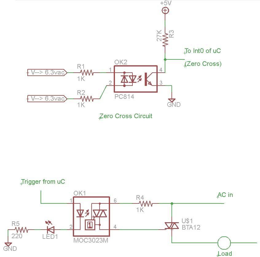
The AVR I am currently using is on a development board but is your basic setup with a 16Mhz Crystal and Max232 for RS232 level conversions.
The 4 outputs are tied to portB 0 - 3
And the Zero-Cross is feeding into INT0 (portD.0 of Mega128)
The program below is the current variation. I finally got the delays working using a timer for the phase delay. I'm still trying to get a good grasp on the timers so there is probably a better way of doing this, but it is functioning.
As usual, any comments or suggestions for improvement or overhead reduction would be welcome.
I know the serial communication portion could probably be optimized. I haven't coded much in this area at all and got it to work as expected after several tries! 
| Code: |
$regfile = "m128def.dat"
$crystal = 16000000
$baud = 19200 ' use baud rate
$hwstack = 32 ' default use 32 for the hardware stack
$swstack = 10 ' default use 10 for the SW stack
$framesize = 40 ' default use 40 for the frame space
'$sim
'_______________________________________________________________________________
Config Portb = Output 'Triacs
Triac1 Alias Portb.0
Triac2 Alias Portb.1
Triac3 Alias Portb.2
Triac4 Alias Portb.3
'_______________________________________________________________________________
Config Pind.0 = Input 'INT0
'_______________________________________________________________________________
Dim T As Byte , T1 As Byte , T2 As Byte , T3 As Byte , T4 As Byte , Tn As Byte , Tt As Byte
Dim Nm As String * 1,
Dim Dig1 As Bit , Dig2 As Bit
'_______________________________________________________________________________
Config Int0 = Rising 'Setup Int0
On Int0 Zero_cross
Enable Int0
Config Timer0 = Timer , Prescale = 8
On Ovf0 Phase_delay
Enable Ovf0
Enable Interrupts
' Initialize variables
T = 1
Tn = 0
T1 = 10
T2 = 20
T3 = 32
T4 = 45
Print "Enter level as 3 digits"
Print "1st digit = Triac#"
Print "Next 2 digits = Level (05{Brightest} - 60{Dimmest})"
Print "Levels below 05 and above 58 may not fire the triac properly."
Print
'Main loop
Do
' Check Serial for incoming data if there is process 1st digit
If Ischarwaiting() = 1 Then
If Tn = 0 Then
Nm = Waitkey()
Tn = Val(nm)
' Make sure Tn falls in range (1-4) if not, reset to zero
If Tn < 1 Then Tn = 0
If Tn > 4 Then Tn = 0
' If we have a valid Triac number, set Dig1 flag
If Tn <> 0 Then Dig1 = 1
End If
End If
' Check Serial for incoming data if there is process 2nd digit
If Ischarwaiting() = 1 Then
' Make sure we 1st have a valid triac number
If Dig1 = 1 Then
' Then process the 10's place for our phase
If Dig2 = 0 Then
Nm = Waitkey()
Tt = Val(nm)
Tt = Tt * 10
' Set Digit 2 flag
Dig2 = 1
End If
End If
End If
' Check Serial for incoming data if there is process 3rd digit
If Ischarwaiting() = 1 Then
If Dig2 = 1 Then
' Reset Digit flags
Dig1 = 0
Dig2 = 0
Nm = Waitkey()
' Create phase for triac based on Triac number (Tn)
Select Case Tn
Case 1:
T1 = Val(nm)
T1 = T1 + Tt
Tn = 0
Case 2:
T2 = Val(nm)
T2 = T2 + Tt
Tn = 0
Case 3:
T3 = Val(nm)
T3 = T3 + Tt
Tn = 0
Case 4:
T4 = Val(nm)
T4 = T4 + Tt
Tn = 0
Case Else:
Tn = 0
End Select
'Un comment to see the ouput numbers (will cause flicker)
'Print "T1 " ; T1
'Print "T2 " ; T2
'Print "T3 " ; T3
'Print "T4 " ; T4
End If
End If
' Fire triacs at phase points.
If T = T1 Then Set Triac1
If T = T2 Then Set Triac2
If T = T3 Then Set Triac3
If T = T4 Then Set Triac4
Loop
Phase_delay:
Load Timer0 33
Incr T
Return
Zero_cross:
Portb = 0
Load Timer0 33
T = 1
Return
|
Rick |
|
| Back to top |
|
 |
elephantshear
Joined: 21 Aug 2009
Posts: 1
Location: Demotte, IN
|
| Posted: Fri Aug 21, 2009 8:24 pm Post subject: |
|
|
Hi Dad
_________________
COOL BEANS! |
|
| Back to top |
|
|
ex4
Joined: 13 Jan 2006
Posts: 1062
Location: indonesia

|
| Posted: Fri Aug 21, 2009 10:43 pm Post subject: |
|
|
nice one
as for the zero cross detector i use 10kohm resistor attached directly to INT0 pin, with 1N4002 diode as clamping diode. the voltage input is from a step down transformer, the transformer also act as psu for my dimmer circuit
that bidirectional optoisolator is rare in my local store,only the unidirectional one like 4N35
just about to post it in my site at
http://ex4-tech.id.or.id |
|
| Back to top |
|
|
Rick-S
Joined: 08 Jan 2009
Posts: 50
|
| Posted: Sat Aug 22, 2009 12:45 am Post subject: |
|
|
LOL, looks like my son found his way into the forum while at school today. He's a Junior in High School this year and is taking a digital electronics class. Maybe he'll teach his old man something!
ex4, is there any advantage to your method of zero cross VS my method? I was curious as I've seen it done both ways. I just opted for this because I had a couple of the PC814 isolators in my parts bin.
BTW, nice website.
Rick |
|
| Back to top |
|
|
mako444
Joined: 02 Jul 2009
Posts: 90
Location: Rio de Janeiro

|
| Posted: Sat Aug 22, 2009 1:14 am Post subject: |
|
|
| Yes ex4, post your schematic here for sharing. |
|
| Back to top |
|
|
ex4
Joined: 13 Jan 2006
Posts: 1062
Location: indonesia
|
| Posted: Sat Aug 22, 2009 5:21 am Post subject: |
|
|
@rick-s:
well for electricity reason : none,hehehe
for simplicity reason : 100% correct
thank you, got no job at the office, so build and post something on the net
here is the schematic |
|
| Back to top |
|
|
mako444
Joined: 02 Jul 2009
Posts: 90
Location: Rio de Janeiro
|
| Posted: Sat Aug 22, 2009 10:45 pm Post subject: |
|
|
Very good, but you should not use a zener diode 5 volts after the 10k resistor on the microcontroller input, I think 16 volts directly at the port can damage the chip.
Which program you used to design the layout? |
|
| Back to top |
|
|
ex4
Joined: 13 Jan 2006
Posts: 1062
Location: indonesia
|
| Posted: Sat Aug 22, 2009 11:53 pm Post subject: |
|
|
as far as i can tell, a pin on the avr will clamp the voltage to max 5V (Vcc). but the current need to be limited, that what 10k resistor are there. for the worse part, 10k can sense directly high voltage upto 220V AC, but for that such high voltage i recommend to use 1Mohm resistor, that should make the avr very safe, although it is in high voltage. High voltage with very minimum or without current at all is harmless,hehehehe 
i use ExpressPCB, its free |
|
| Back to top |
|
|
Rick-S
Joined: 08 Jan 2009
Posts: 50
|
| Posted: Sun Aug 23, 2009 1:06 pm Post subject: |
|
|
Atmel's Datasheet AVR182 shows this can be done without regulation directly off the mains.
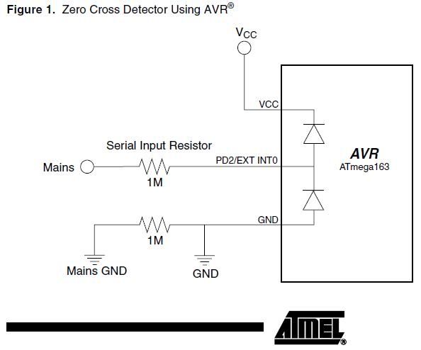
This is a clip from that datasheet showing an example circuit. Here is a link to the full datasheet.
The document does go along with what ex4 stated:
| Quote: | To protect the device from voltages above VCC and below GND, the AVR has internal
clamping diodes on the I/O pins (see Figure 1). The diodes are connected from the pins
to VCC and GND and keep all input signals within the AVRs operating voltage (see Figure
2). Any voltage higher than VCC + 0.5V will be forced down to VCC + 0.5V (0.5V is the
voltage drop over the diode) and any voltage below GND - 0.5V will be forced up to
GND - 0.5V. |
Even though the chips were designed with this in mind, I just feel nervous having voltage higher than 5vdc pumped into my controllers. Other than the fact the optoisolators were in my parts bin, that was my other reason for using them. |
|
| Back to top |
|
|
ex4
Joined: 13 Jan 2006
Posts: 1062
Location: indonesia
|
| Posted: Sun Aug 23, 2009 4:22 pm Post subject: |
|
|
yup, thats why i tap it from a transformer rather than directly to the hot side
got freaking horrible experience with HVDC system long time ago
yup, that was a big wuuuuuuuuu  |
|
| Back to top |
|
|
mako444
Joined: 02 Jul 2009
Posts: 90
Location: Rio de Janeiro
|
| Posted: Mon Aug 24, 2009 1:20 am Post subject: |
|
|
| good, I had this information, thank you. |
|
| Back to top |
|
|
|


