90S2313 Alarm Clock
This application note was submitted by Nick
Baroni.
This Ap Note
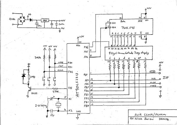
describes a time clock switch with individually setable on and off
times. It is based on a AT90LS2313 and a surplus nine digit common
cathode 7 segment LED display such as those found in older calculators
Design notes:
The hardware is described in figure 1. The heart of the unit is a
AT90LS2313 run at 2.4576 MHz. A 74HC595 shift register sinks the
cathode current from the display. The LED display has tiny (~3mm high)
digits and the segment current is about 1.8 mA, set by the 1.8k anode
resistors. Even with all digits in a segment on, the resulting 12mA is
within the capabilities of the 595.
The cathode of digit 1 is connected to PortD.6 of the 2313. The 595's
shift register and latch clocks are tied together. This has the effect
of delaying the output and the data input by one clock cycle. Advantage
of this is taken in the code.
Three push buttons provide mode and time setting control. The mode
switch cycles the control mode between 'run', 'set', 'on' and 'off'.
In the run mode, the slow and fast buttons either turn on or off the
load. In the other modes, they increment the time settings. I elected
to provide external pull ups rather than enable the internal ones.
An accuracy of 1 second per day implies a frequency accuracy of 1/86400
or 11.6 ppm. Most common CPU crystals are not this accurate and a small
trimmer is used on Xtal1 to tune the frequency.
The display is multiplexed. This means that only one of the nine digits
is turned on at any time. In order to stop the display flickering, it
is important to update each digit quickly enough to allow persistence
of vision to make the observer think that all digits are on
continuously.
The timer0 overflow interrupt is used to do the display update and
count off the time. The crystal used needs to be able to be divided
down to exactly one second other wise the clock won't keep accurate
time.
The 2457600 Hz clock is divided by 64 to 38400 Hz. Timer 0 is preloaded
with 160 every interrupt. This makes timer0 divide by 96 (160 + 96 =
256). The resultant interrupt rate is then 400 Hz.
When the program isn't updating the display, it reads and reacts to the buttons and calculates the display contents.
The following compiler settings were used for this project.
Stacksize=56
Framesize=32
Sstack=8
Figure 1
' Clock/timer on 9 digit common
cathode muxed display
' N Baroni
' Dec 03
' Port B segment anodes
' PB0 - c
' PB1 - dp
' PB2 - a
' PB3 - e
' PB4 - d
' PB5 - g
' PB6 - b
' PB7 - f
' PD6 Digit 1 cathode
' PD5 - Cathode SR Data
' PD4 - Cathode SR Clk
' PD3 - Switch out
' PD2 - Right button
' PD1 - Middle button
' PD0 - Left button
' Display Digit Cathodes Are On A 595 with Sclk&Rclk
connected togther
' So latch outputs are always one step behind what the SR
is doing.
' At digit 1, shift one zero into the SR then toggle the
clock at sucessive
' digits with srdata high.
$regfile = "2313def.dat"
$crystal = 2457600
Digit1 Alias Portd.6
Ksrdata Alias Portd.5
Ksrclock Alias Portd.4
Switchout Alias Portd.3
Rbut Alias Pind.2
Mbut Alias Pind.1
Lbut Alias Pind.0
Dim Displayram(9) As Byte
Dim Disdigit As Byte
Dim Displaymode As Byte
Dim Dayminutes As Word , Seconds As Byte
' Day is 24*60 = 1440 minutes
Dim Alarmon As Word , Alarmoff As Word
Dim Ticks As Integer
Dim Overflowvalue As Integer
Dim Isupdate As Bit
Dim Itemp As Integer
Declare Sub Time2mem(byval S As Word)
Declare Sub Changemode
Ddrb = &B11111111
Ddrd = &B01111000
'turn off all cathodes
Ksrdata = 1
For Disdigit = 1 To 9
Set Ksrclock
Reset Ksrclock
Next
Digit1 = 1
Disdigit = 1
'init
Displaymode = 1
' Crystal is 2457600. Prescale of 64 = 38400 at counter
input
' preloading with 160 overflows in 96 counts
' 38400/96 = 400
' so have 400 overflows per second.
' One digit per overflow interrupt - 44.44 Hz
Config Timer0 = Timer , Prescale = 64
On Timer0 Muxservice
Enable Timer0
Enable Interrupts
Start Timer0
'Main loop
Do
Debounce Lbut , 0 , Changemode , Sub
If Displaymode = 1 And Mbut = 0 Then
Set Switchout
' Displayram(1).1
= 1
' Displayram(2).1
= 1
' Displayram(3).1
= 1
End If
If Displaymode = 1 Then
If Rbut = 0 Then Reset Switchout
' Displayram(1).1
= 0
' Displayram(2).1
= 0
' Displayram(3).1
= 0
Displayram(1) = 40 'r
Displayram(2) = 217 'u
Displayram(3) = 205 'n
Call Time2mem(dayminutes)
End If
If Displaymode = 2 Then
If Isupdate = 0 Then
If Mbut = 0 And Rbut = 0 Then
Dayminutes = Dayminutes + 60
Else
If Mbut = 0 Then Dayminutes
= Dayminutes + 10
If Rbut = 0 Then Dayminutes
= Dayminutes + 1
End If
If Dayminutes >= 1440 Then Dayminutes = 0
End If
Isupdate = 1
Displayram(1) = 181 's
Displayram(2) = 188 'e
Displayram(3) = 140 't
Call Time2mem(dayminutes)
End If
If Displaymode = 3 Then
If Isupdate = 0 Then
If Mbut = 0 Then Alarmon = Alarmon + 10
If Rbut = 0 Then Alarmon = Alarmon + 1
If Alarmon >= 1440 Then Alarmon = 0
End If
Isupdate = 1
Displayram(1) = 57 'o
Displayram(2) = 41 'n
Displayram(3) = 0
Call Time2mem(alarmon)
End If
If Displaymode = 4 Then
If Isupdate = 0 Then
If Mbut = 0 Then Alarmoff = Alarmoff + 10
If Rbut = 0 Then Alarmoff = Alarmoff + 1
If Alarmoff >= 1440 Then Alarmoff = 0
End If
Isupdate = 1
Displayram(1) = 57 'o
Displayram(2) = 172 'f
Displayram(3) = 172 'f
Call Time2mem(alarmoff)
End If
Loop
'-------------------
Sub Changemode
'step through
available modes with LH button press.
Incr Displaymode
If Displaymode = 5 Then Displaymode = 1
End Sub
'-------------------
Sub Time2mem(byval S As Word)
'take time and put in digits 4:9
Local Btemp As Byte , Wtemp As Word , Didx As Byte , Idx As Byte
For Idx = 1 To 2
Wtemp = S Mod 10
Btemp = Lookup(wtemp , Chars)
Didx = 2 * Idx
Didx = 10 - Didx
Displayram(didx) = Btemp '1,2 -> 8,6
S = S 10
Wtemp = S Mod 6
Btemp = Lookup(wtemp , Chars)
Didx = 2 * Idx
Didx = 9 - Didx
Displayram(didx) = Btemp '1,2 ->7,5
S = S 6
Next
Displayram(6).1 = 1
Btemp = Seconds Mod 6
Btemp = Lookup(btemp , Squiggle)
Displayram(9) = Btemp
End Sub
'--------------------------------------
Muxservice:
'Timer 0 interrupt routine.
' occurs at 400 Hz. On each interrupt, do clock thing,
' calcuate display contents, display next digit
' Display digit freq = 400/9 = 44.44 Hz
' Do time keeping thing
Tcnt0 = 160
Incr Ticks
If Ticks > 400 Then
Ticks = 0
Incr Seconds
If Seconds = 60 Then
Seconds = 0
Incr Dayminutes
If Dayminutes = 1440 Then
' New day
Dayminutes = 0
End If
End If
' Check alarm
times
If Dayminutes = Alarmon Then Set Switchout
If Dayminutes = Alarmoff Then Reset Switchout
End If
' Quarter second auto increment
Itemp = Ticks Mod 100
If Itemp = 50 Then
Isupdate = 0
End If
' Push next digit out to display
Portb = 0
If Disdigit = 1 Then
Digit1 = 0
Ksrdata = 0
Else
Digit1 = 1
Ksrdata = 1
End If
Set Ksrclock
Reset Ksrclock
Portb = Displayram(disdigit)
Incr Disdigit
If Disdigit = 10 Then Disdigit = 1
Return
'End of timer0 interrupt routine
Chars:
' b76543210
' fbgdeapc
'0: abcdef -
0b11011101 = 221
'1: bc -
0b01000001 = 65
'2: abged -
0b01111100 = 124
'3: abgcd -
0b01110101 = 117
'4: fbgc -
0b11100001 = 225
'5: afgcd -
0b10110101 = 181
'6: cdefg -
0b10111001 = 185
'7: abc -
0b01000101 = 69
'8: abcdefg - 0b11111101 = 253
'9: abcfg -
0b11100101 = 229
Data 221 , 65 , 124 , 117 , 225 , 181 , 185 , 69 , 253 , 229
Squiggle:
'abcdef
Data 4 , 64 , 1 , 16 , 8 , 128
' b76543210
' fbgdeapc
'A: abcefg -
0b11101101 = 237
'E' adefg -0b10111100 = 188
'F; aefg -0b10101100 = 172
'n: ceafb -0b11001101 = 205
'o: cdeg -0b00111001 = 57
'r: efa -
0b10001100 = 140
's: afgcd -
0b10110101 = 181
't: efa -
0b10001100 = 140
'u' cdefb -0b11011001 = 217
Download source code
|


