FAT16 File System Driver for CompactFlash
Application Notes by: Larry Wolcott
email: objectcoder@hotmail.com
web: http://www.larrywolcott.com
Before I begin, it is ABSOLUTELY required that you set the "frame
size" to a higher number in Options, Compiler->Chip->Frame
Size. I use 256 to be safe but 128 would be fine I'm sure. I'm putting this here
so you read this first and not email because it's not working properly!
So, you must be interested in using CompactFlash as a storage media for your
project.
Naturally, this is appealing for many applications including web servers, data
loggers, and the list goes on. After reading "Application
Notes 123", I was convinced that I had solved my high capacity storage
problem. I spent an entire weekend with soldering pencil with a few trips to
Radio Shack and got the hardware interface working. I happened to have some
CompactFlash headers in my parts box so I only needed a few other things. Some
10 wire ribbon cable w/ connectors, PC board, 10K resistor (for pull-up) and
some patience.
Using .5 mil magnet wire from Radio Shack, I carefully pulled away the CF header
pins and soldered the "monkey wire" (seen as red in figure 1, below).
Then, I wired 3 10-pin ribbons with connectors so it could be easily connected
to the Atmel STK500/501 (STK500 with the 501 daughter board) seen in figure 2
below. This simple hardware interface was developed using the AN123
documentation.
For convenience, I have included the schematic seen as figure 3 below. Having
this interface is a requirement of the FAT16 driver. Conversely, the FAT16
filesystem driver requires that the CompactFlash (CF) device driver from AN123
be included in your project. The file name is FlashCardDrive.bas and has been
included in this distribution with permission of the author, Josef Franz Vögel.
I will not spend much time discussing the hardware as that is covered nicely in
Josef's AN123. I will however include pictures of my implementation so you all
can enjoy my handy work (grin). As a side note, you might consider ordering a CF
to IDE adapter to save time. I own one of these and it would work with some
modification. Keep in mind that these are designed for 16 bit transfers in IDE
mode, and our interface is 8 bit memory mode. It will require cutting some
traces and jumping a few others. Here is where I purchased mine: http://www.acscontrol.com/Index_ACS.asp?Page=/Pages/Products/CompactFlash/IDE_To_CF_Adapter.htm.
I decided to fabricate my own so I would not have to sacrifice such a nice
device for the cause. In the following documentation, I will discuss FAT16 in
sometimes painful detail. If you do not care about the underlying
implementation, feel free to skip all the way down to the pretty pictures. :-)
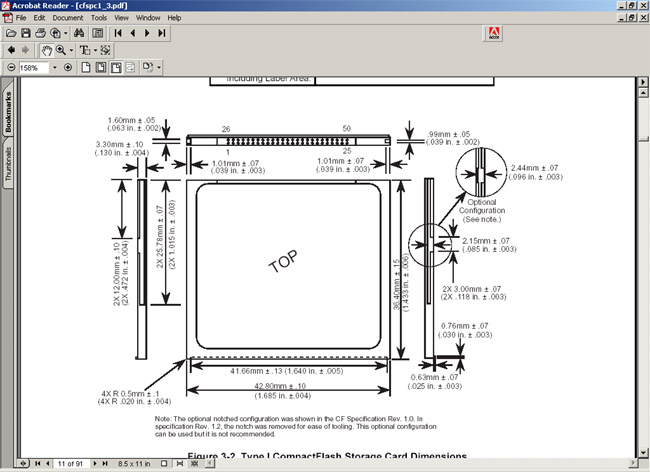
NOTE: Be mindful of the proper CF header pin specification! see Figure 4 for the
proper pin-out.
I will begin by discussing File Allocation Tables (FAT) in three forms, FAT
12, FAT16 and FAT32. The specific flavour of FAT to be used is determined by the
size of the media contrary to popular belief. The 12, 16 and 32 refer to
the size of the cluster value in bits (although FAT32 is really 28 bits because
4 are reserved). Hopefully, you understand at this point that the storage device
is divided in to a fundamental blocks of data called a sector. While sectors can
be many sizes, they are almost always 512 bytes. So, a CF card with 64M capacity
would have (64,000,000 / 512) = 125,000 sectors give-or-take a few. Refer to the
following table:
| |
FAT12 |
FAT16 |
FAT32 |
| Used For |
Floppies and small hard disk volumes |
Small to large hard disk volumes |
Medium to very large hard disk volumes |
| Size of Each FAT Entry |
12 bits |
16 bits |
28 bits |
| Maximum Volume Size |
16 Meg |
2 Gig |
about 2^41 |
That being said, this driver currently only supports FAT16 which means
you must use as CF greater than 16Meg and less than 2Gig in capacity. Which
brings us to one of the attractions of using CompactFlash as a storage media.
Price! Along with the many other good reasons, of course.
So, there are a lot of sectors to keep track of. When your file spans
multiple sectors, how does the filesystem know which ones are linked together?
Well, it groups the sectors together in a gang called a cluster. Cluster is a
group of sectors that are grouped together because it is too hard to keep track
of every single sector. In the case of my 64Meg CF card, a cluster is made up of
2 sectors (2 sectors @ 512 each) = 1K per cluster. On my 256 Meg CF card, the
cluster size is 8 sectors (8 sectors @ 512 each) = 4K. Cluster sizes are
determined by the OS at the time of formatting based on the volume size. See the
table below:
| Volume size |
FAT16 cluster size |
FAT32 cluster size |
NTFS cluster size |
| 7 MB16 MB |
2 KB |
Not supported |
512 bytes |
| 17 MB32 MB |
512 bytes |
Not supported |
512 bytes |
| 33 MB64 MB |
1 KB |
512 bytes |
512 bytes |
| 65 MB128 MB |
2 KB |
1 KB |
512 bytes |
| 129 MB256 MB |
4 KB |
2 KB |
512 bytes |
| 257 MB512 MB |
8 KB |
4 KB |
512 bytes |
| 513 MB1 GB |
16 KB |
4 KB |
1 KB |
These clusters are linked together in a cluster chain. The FAT has an area
that maps each cluster and the address of the next cluster in the chain. This is
the same concept used in in C++ and Java for LinkedList and others. When the OS
is finished reading the first cluster (2 sectors in my case, 1K byte), it refers
to the FAT to determine the next cluster to read for the file. As a side note,
this FAT16 implementation does not properly follow a cluster chain. I
have cheated because my requirements are much simpler. This driver identifies
the starting cluster and reads each subsequent cluster in a linear manner.
Meaning, if the file starts at cluster 02 and the file length is 4K bytes, it
will read cluster 02, 03, 04 and 05 without referring to the cluster chain
defined in the table. It assumes that there is no fragmentation on the CF
device. Warning: To avoid problems with cross linking cluster chains,
either fix the code or format the device after it reaches max capacity! Also,
avoid deleting files- just format the device when you want to renew the
capacity.
Now that we have covered the basics about sectors and clusters, I will
discuss the physical sector layout. The device has quite a few fundamental areas
that contain pieces of important information. These areas are all read to
determine the file info, cluster chains, data areas, etc. Each is described
below, shamelessly plagiarized from http://home.teleport.com/~brainy/fat16.htm.
Each of these disk areas are read in the following order.
1. Master Boot Record (MBR)
The MBR is always located at sector 0 on the device. All other sector/cluster
locations are derived from information starting here. The 512 byte MBR is made
up of the following information. This is the first sector read to determine the
starting sector for the 1st volume on the device.
| Offset |
Description |
Size |
| 000h |
Executable Code (Boots Computer) |
446 Bytes |
| 1BEh |
1st Partition Entry (See Next Table) |
16 Bytes |
| 1CEh |
2nd Partition Entry |
16 Bytes |
| 1DEh |
3rd Partition Entry |
16 Bytes |
| 1EEh |
4th Partition Entry |
16 Bytes |
| 1FEh |
Executable Marker (55h AAh) |
2 Bytes |
To be practical, this implementation only cares about the 1st partition table
and ignores the executable code, 2nd, 3rd and 4th. This is the 16 bytes from the
partition table:
2. 1st Partition Table (bytes 447 - 462 of the MBR)
The partition table details the partition type (FAT12, FAT16, etc), starting
sector, number of sectors, etc. Once the driver know where the first volume
starts on the device (which sector to start reading) we can obtain the location
of the Volume Boot Record.
| Offset |
Description |
Size |
| 00h |
Current State of Partition (00h=Inactive,
80h=Active) |
1 Byte |
| 01h |
Beginning of Partition - Head |
1 Byte |
| 02h |
Beginning of Partition - Cylinder/Sector (See
Below) |
1 Word |
| 04h |
Type of Partition (See List Below) |
1 Byte |
| 05h |
End of Partition - Head |
1 Byte |
| 06h |
End of Partition - Cylinder/Sector |
1 Word |
| 08h |
Number of Sectors Between the MBR and the
First Sector in the Partition |
1 Double Word |
| 0Ch |
Number of Sectors in the Partition |
1 Double Word |
3. Volume Boot Record (FAT12 & FAT16)
The Volume Boot Record (referred to as the Boot Record) contains more of the
volume specific information required to locate information on the device. From
here, we can determine the location of the root directory, cluster tables, # of
sectors in the partition, volume name, etc.
| Offset |
Description |
Size |
| 00h |
Jump Code + NOP |
3 Bytes |
| 03h |
OEM Name |
8 Bytes |
| 0Bh |
Bytes Per Sector |
1 Word |
| 0Dh |
Sectors Per Cluster |
1 Byte |
| 0Eh |
Reserved Sectors |
1 Word |
| 10h |
Number of Copies of FAT |
1 Byte |
| 11h |
Maximum Root Directory Entries |
1 Word |
| 13h |
Number of Sectors in Partition Smaller than
32MB |
1 Word |
| 15h |
Media Descriptor (F8h for Hard Disks) |
1 Byte |
| 16h |
Sectors Per FAT |
1 Word |
| 18h |
Sectors Per Track |
1 Word |
| 1Ah |
Number of Heads |
1 Word |
| 1Ch |
Number of Hidden Sectors in Partition |
1 Double Word |
| 20h |
Number of Sectors in Partition |
1 Double Word |
| 24h |
Logical Drive Number of Partition |
1 Word |
| 26h |
Extended Signature (29h) |
1 Byte |
| 27h |
Serial Number of Partition |
1 Double Word |
| 2Bh |
Volume Name of Partition |
11 Bytes |
| 36h |
FAT Name (FAT16) |
8 Bytes |
| 3Eh |
Executable Code |
448 Bytes |
| 1FEh |
Executable Marker (55h AAh) |
2 Bytes |
4. Directory Table (FAT12 & FAT16)
Contains file, directory and volume information for the ROOT directory. Again,
for the sake of simplicity, I have not implemented Long File Names aka
(VFAT or LFN). These are stored in sequenced directory entries and exceed the
scope of my requirements. For that reason, you are required to use a max of 8
character file names plus the 3 character extension. i.e. TESTFILE.TXT or
FILE1.DAT and not "SomeLongFileName with spaces.txt". Likewise, we
only deal with files on the root directory because I have not implemented
directories.
| Offset |
Length |
Value |
| 0 |
8 bytes |
Name |
| 8 |
3 bytes |
Extension |
| 11 |
byte |
Attribute (00ARSHDV)
0: unused bit
A: archive bit,
R: read-only bit
S: system bit
D: directory bit
V: volume bit |
| 22 |
word |
Time |
| 24 |
word |
Date |
| 26 |
word |
Cluster (desc. below) |
| 28 |
dword |
File Size |
5. Cluster map for FAT16 (16 bit values (2 bytes), 256 entries per 512
byte sector)
The cluster map contains 2 byte entries used to identify the next cluster
that belongs to the chain. Note that cluster entries 00 and 01 are always
reserved. The first cluster that can be used on a newly formatted disk would be
02. So a cluster map might look like this for a single file that is 4K bytes in
length: (remember that my 64 Meg card has 1K clusters each being 2 sectors @ 512
bytes).
| Clust 00 |
Clust 01 |
Clust 02 |
Clust 03 |
Clust 04 |
Clust 05 |
Clust 06 |
Clust 07 |
| 00 00 |
00 00 |
03 00 |
04 00 |
05 00 |
FF FF |
00 00 |
00 00 |
The entries for cluster 00 and 01 are reserved, hence the 00 values. The file
starts at cluster 02 so that entry points to 03 as the next cluster in the chain
and so on. Finally, the file ends at cluster 05 which explains the FF FF values
which represents a termination in the cluster chain. This would look exactly the
same if the file length were 3200 bytes instead of 4000. The remaining 800 bytes
in the last cluster are wasted space. This is a side-effect of using FAT file
systems- the larger the cluster size, the more potential wasted space.
Figure 1, homemade CompactFlash interface for use with AVR (or any)
MCU.
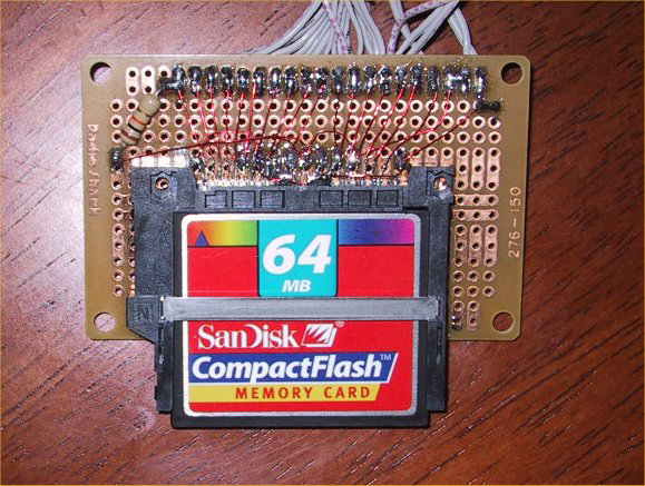
Figure 2, CompactFlash interface connected to the Atmel STK500 with the
STK501 installed.
NOTE: 4Mhz xtal installed for use with the Atmega103
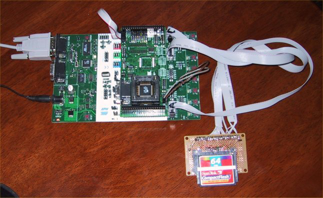
Figure 3, CompactFlash schematic borrowed from "Application Notes
123". (thanks Joesf!)
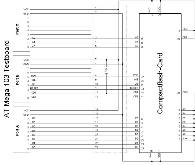
Figure 4. Proper pin orientation for the CF
Now, on to the code! I have included two modules. FlashCardDrive.bas is the
low-level ASM device driver for the compact flash. This is used by the
high-level FAT16Driver.bas file. Due to the late hour and my lack of rest, this
section will be somewhat abbreviate. I have also included a simple test file
named DriverTest.bas. This code will demonstrate some of the basic functions of
the FAT driver. I will start with the low-lever commands:
Print "V1.0 Setup Port and Reset Card ... ";
If Drivecheck() = 1 Then

Driveinit

Else

Print #1 , "Card not inserted, check Card!"

End

End If
This sequence is used to check the state of the card (implemented with
the 10K pull-up resistor). If the card is inserted, driveinit is called to set
up the interface. Next,
'debug info

Print "DriverTest Starting."
'read the mbr

Call Init()

'more debug info

Print "Finished DriverTest."
Tells the FAT driver to read the Master Boot Recotd (MBR), partition table
and boot record, in that order. This data is required to locate the various
areas of the disk like the cluster maps, directory entries, data area, etc. At
this point, you should see some output like this:
V1.0 Setup Port and Reset Card ... OK

DriverTest Starting.

Init()

Reading MBR at Sector: 0

File System Type: 06

Start Sector: 32

Filesystem: FAT16

ReadBootRecord()

Reading from Sector 32

Bytes per sector: 512

Sectors per cluster: 2

Sectors per fat: 244

Reserved sectors: 1

Copies of fat: 2

Max root entries: 512

FindLastUsedSector()

Finding Last Used Cluster starting at: 521

Setting last used cluster to: 2

Finished DriverTest.
As you can see, the driver reads all of the appropriate sector information
and finally scans the disk to determine the next available cluster to be used
for writing. Next, we will use the Createorappendtofile(filename)
function to start appending (will create a new file if it does not already
exist) to a file named "NEWFILE.TXT" followed by a subsequent
writedata("SOME STRING DATA", 1) to append a string to the file. Then,
we will use the listfile(filename) command to dump the contents of
the file to the RS232. NOTE: I hard coded bogus file creation time/date instead
of leaving it blank.
'create a file on the root directory

Call Createorappendtofile( "NEWFILE.TXT")
'write some data to the file

Ercode = Writedata( "The quick brow fox jumped over the lazy dog!" ,
1)
'list the file contents

call Listfile( "NEWFILE.TXT")
This is the expected output:
V1.0 Setup Port and Reset Card ... OK

DriverTest Starting.

Init()

Reading MBR at Sector: 0

File System Type: 06

Start Sector: 32

Filesystem: FAT16

ReadBootRecord()

Reading from Sector 32

Bytes per sector: 512

Sectors per cluster: 2

Sectors per fat: 244

Reserved sectors: 1

Copies of fat: 2

Max root entries: 512

FindLastUsedSector()

Finding Last Used Cluster starting at: 521

FAT start sector:521 for dir entries

Searching for NEWFILE.TXT

File: NEWFILE.TXT not found

First cluster entry- setting to 2

Empty dir entry at location 1 on sector 521

Reading allocation table at sector: 33

setting 2 bytes at 5

Writing allocation table at sector: 33

Writing 44 bytes: 'The quick brow fox jumped over the lazy dog!'

Adding 2 byte linefeed to text

Loading data buffer to write

Writing sector 553 sectinclust: 1

Setting the directory entry values

Writing the directory entry values

FAT start sector:522 for dir entries

Searching for NEWFILE.TXT

Dumping File, sect: 553 bytes: 46

Total sec: 0 mod: 46 bytes

The quick brow fox jumped over the lazy dog!
*EOF*

Finished DriverTest.
Wow! bet you didn't expect that much work to write a file? Ok.. Soooo.
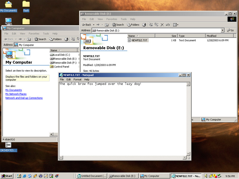
This is what you've all been waiting for. I'll take the CompactFlash and read
with my Windows 2000 PC and this is the end game:
On that note, will wrap up my FAT16 reference implementation notes. Please
use this code and documentation in any way you see fit. I must also point out
that there has been almost NO TESTING done on this code what so ever. I will
tell you that I even fried a 256 Meg Sandisk in the early phases of my
development :-) fortunately I saved the receipt. Use at your own risk!
Cheers and good luck!
-Larry Wolcott
Download the BASCOM source code from (with fix for huge files) |