Download source codes
Abstract
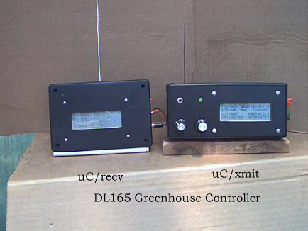
The design of this GREENHOUSE CONTROLLER
consists of two units, the microcontroller/transmitter (uC/xmit) and the
microcontroller/receiver (uC/recv).
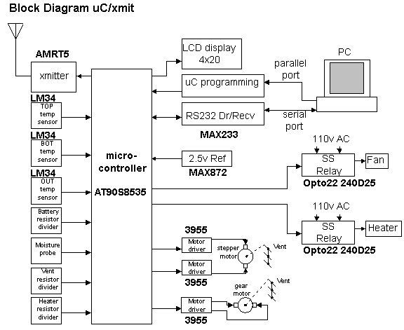
The uC/xmit unit is located in the greenhouse while the uC/recv is located in
the house about 75 feet from the greenhouse.
The uC/xmit units gathers data from temperature sensors and based on this data
operates two vents, heater and a fan. The unit then transmits the temperature
data and the state of the vents, heater and fan utilizing the license free
433.9MHz band.
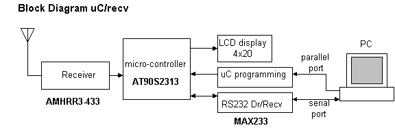
This information is also displayed on a 4x20 LCD in the unit. The uC/recv unit
receives and displays the same information on a similar LCD. This process is
repeated every 10 seconds.
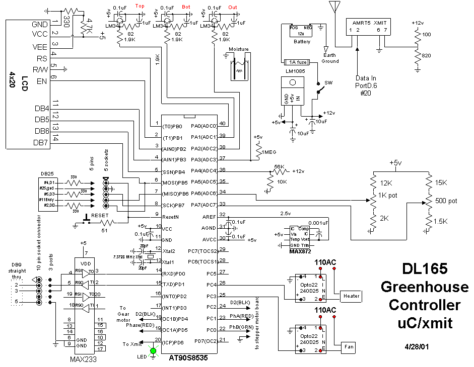
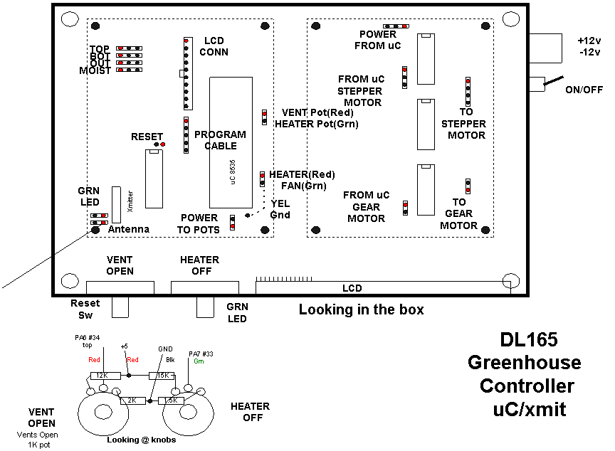
The uC/xmit unit employs three
temperature sensors whose outputs are monitored by the ADC within the AT90S8535
uC.
The TOP temperature sensor, located near the top of the greenhouse, determines
the state of the vents while the BOT temperature sensor, located near the bottom
of the greenhouse, determines the state of the heater. The state of the fan is
dependent on the state of the vents and the TOP temperature.
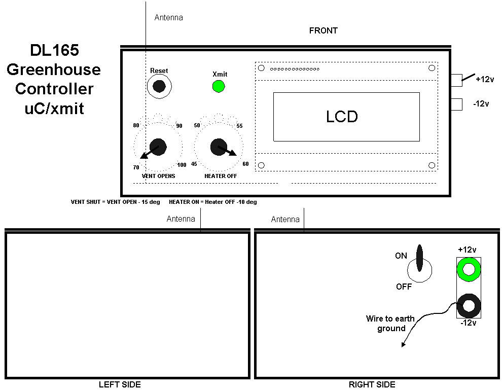
The uC/xmit unit utilizes potentiometers so that both the temperature at which
the vents open and the heater turns on are adjustable.
The vents open temperature range is from 69 deg F to 105 deg F. The vents
will shut 15 deg F below the set vents open temperature. The heater on
temperature range is from 24 deg F to 50 deg F and the heater will turn off 10
deg F above the set heater on temperature.
The fan will turn on 10 deg F above the vents open temperature and turn off 5
deg F above the vents open temperature. Presently the uC/xmit is powered by a 12
volt battery, which is also monitored by the uC/xmit unit.
The monitored range is from 0 to 18.8 volts. There is also a temperature sensor,
OUT, mounted outside the greenhouse. Both the battery voltage and OUT
temperature is also transmitted to the uC/recv. The soil moisture in a test
container is monitored as either High or Low. The uCxmit unit will send an
emergency message to the uC/recv if either of the following occurs and at which
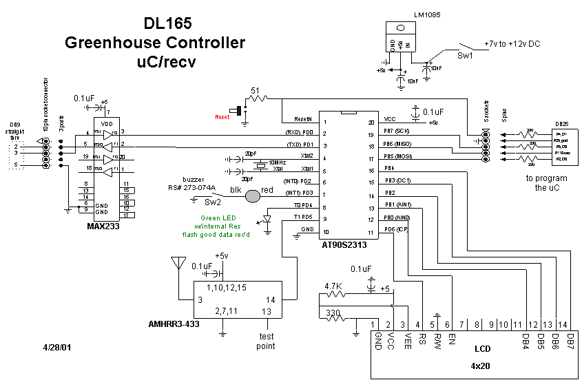
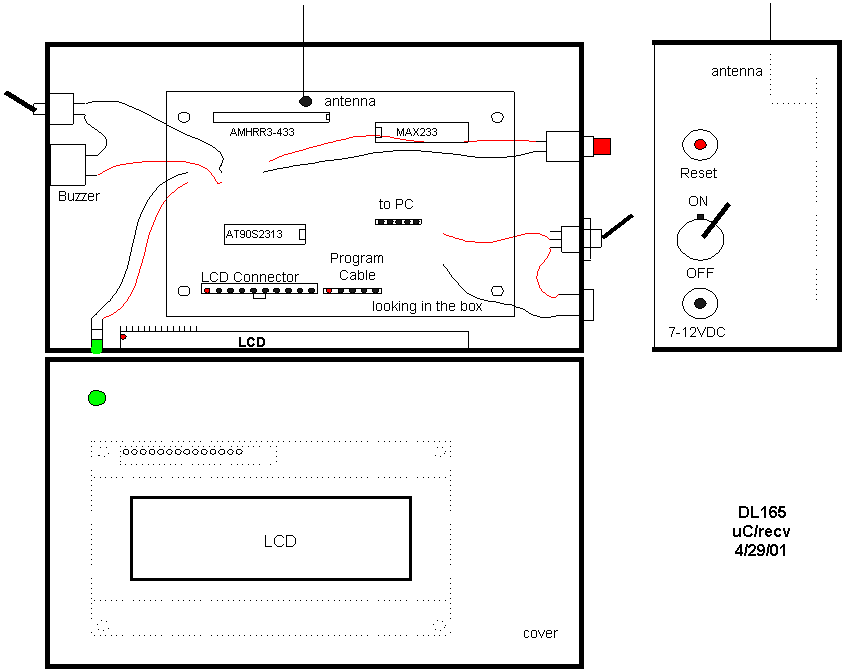
time the uC/recv, which utilizes the AT90S2313 uC, will turn on a buzzer, flash
the display and turn on an LED. This condition will persist until the condition
is corrected. During normal reception, the LED only blinks after valid data is
received.
1) if TOP <= 32deg OR => 110deg
2) if BOT <= 32deg OR => 99deg
3) if Battery voltage < 9.1 volts
Both the uC/xmit and uC/recv units
display the same information in the following format.
TOP=102 VENT76-91=O
BOT=99 M=H FAN=ON
OUT=106 BATT=12.8
HTR=47-57 HEAT=OFFx
The following is an explanation of the
data displayed.
TOP, BOT and OUT are the respective
sensor temperature readings in degrees Fahrenheit.
VENT76-91=O indicates that the pot for
the vents is set to open the vents when TOP temperature is =>91 deg F and 15
deg less (76) the vents will shut, the O indicates that the vents are open.
M=H FAN=ON indicates High soil moisture
in the test container and the fan is on since the TOP temperature is greater
than 10 deg F above the vents open temperature (91).
The BATT=12.8 indicates that the voltage
of battery supplying power to the uC/xmit unit is 12.8 volts.
HTR=47-57 indicates that the pot for the
heater is set to turn on the heater at 47 deg F and 10 deg greater (57) the
heater will turn off.
HEAT=OFFx indicates that the heater is
off since the BOT temperature (99) is greater than the heater turn off
temperature (57). The x is a number from 0 to 9 that is transmitted and
displayed on the uC/recv display so that it can be determined whether sequential
transmissions are being received.
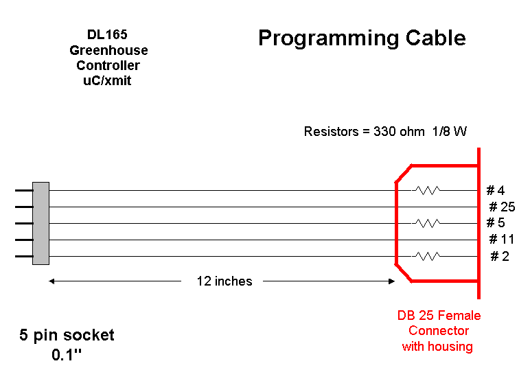
BASCOM-AVR software was used to write
and compile the programs for both units. The uC/xmit program has statements so
that the fan will not turn on if the vents are shut and the heater will not turn
on if the vents are open.
The uC/recv program has a safe guard in that it will not accept data unless a
Synch code is received.
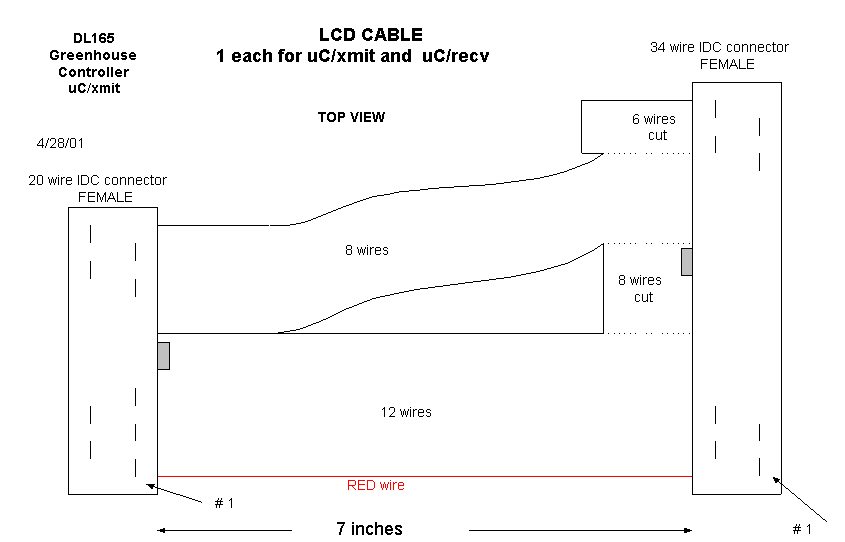
An RS232 interface (MAX233) is provided in both units so that data can be sent
(with program modifications) to a PC for processing. The uC/xmit was built on 2
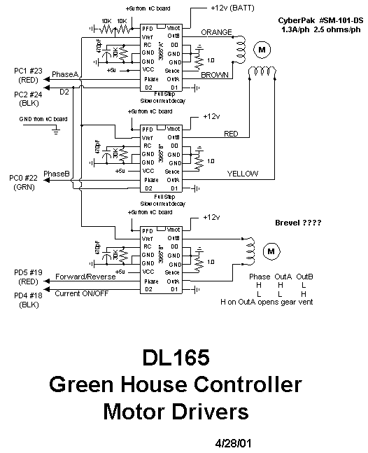
Radio Shack proto boards, one for the uC, RS233 interface, 5v reg and 2.5v ref
and one for the 3 motor controller chips Allegro 3955 while
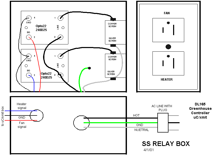
the uC/recv was built on one board. The solid state relays were mounted in a
separate box with an AC receptacle for the fan and heater.