BASCOM-AVR Hotchip cable
Application note provider by Mark
Voevodin
I
recently downloaded BASCOM-AVR (http://www.mcselec.com)
to try with the Hotchip AVR (http://www.hawknet.com.au/~invtech). Dick Smith in Australia distributes the Hotchip, and I believe there are
other distributors overseas.
I found a pin out diagram for the
Sample Electronics programmer on Dontronics web page. By comparing the pin outs for Hotchip with Sample Electronics I
determined that only two pins are different. Pin 3 on Hotchip is same as Pin 5 on Sample Electronics, and Pin 10 is
same as Pin 11. I have made a
crossover 25-pin plug that swaps these pins, and I can now use Bascom-AVR to
program the Hotchip (using original parallel cable supplied with the Hotchip). I could have modified the original cable, but I wanted to be able to use
the original ABC software that came with the Hotchip. This design allows me to
do both. The reverse pin outs could be used to allow the ABC software to be used
with other AVR modules.
BASCOM-AVR {Sample Electronics config} to Hotchip AVR
cable
Connect a wire
from the DB25M pin 2 to the DB25F pin 2
Connect a wire
from the DB25M pin 4 to the DB25F pin 4
Connect a wire
from the DB25M pin 5 to the DB25F pin 3
Connect a wire
from the DB25M pin 11 to the DB25F pin 10
| DB25Maleconnector
|
DB25Femaleconnector
|
Description |
| Pin 2, D0 |
Pin 2, D0 |
MOSI
|
| Pin 4, D2 |
Pin 4, D2 |
RESET
|
| Pin 5, D3 |
Pin 3, D1 |
CLOCK
|
| Pin 11, busy |
Pin 10 |
MISO
|
| Pin 18-25,
ground |
Pin 18-25,
ground |
GND
|
Note that pin
18, 19, 20, 21, 22, 23, 24 and 25 of the DB25 male connector must be connected
to pin 18, 19, 20, 21, 22, 23, 24 and 25 of the DB25 female connector. Other
pins can be optionally connected straight through.
The DB25M
connector matches the simple cable programmer design from Sample Electronics.

Based on diagram found at
http://www.dontronics.com/runavr.html
DB25Male side of this adapter goes into parallel port, original Hotchip
parallel programming cable plugs into the DB25Female side.
Set BASCOM-AVR to use Sample Electronics
programmer and you are ready to go!
As an alternative you can select
the Hotchip programmer from the Universal MCS Programmer Interface. Mark Voedin
has created the settings and tested them.
Here
is Mark's tip:
Add the following lines to the file prog.settings
[HotChip]
;tested and ok
BASE=$378
MOSI=BASE,1
CLOCK=BASE,2
RESET=BASE,4
MISO=BASE+1,64
Save these changes.
Start BASCOM, Select the Universal MCS Programmer Interface and
select the HotChip entry you created.
After you have selected an entry, save your settings and exit BASCOM. At
the next startup of BASCOM, the settings will be used.
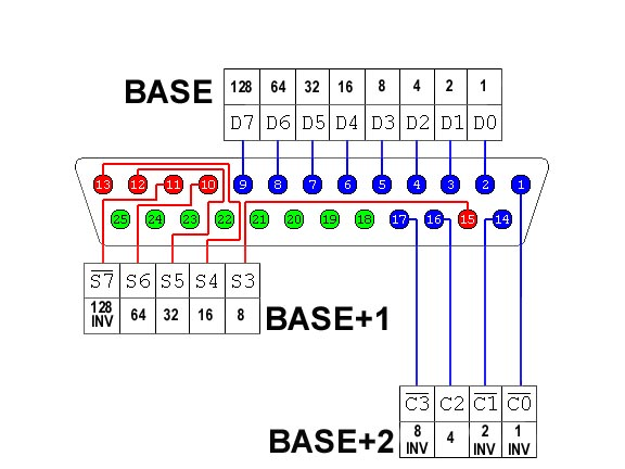
The
following picture of the LPT port connector and related registers is very handy
:
Mark Voevodin
marner@ozemail.com.au
|


