Measuring temperature with 90S2313 and BASCOM-AVR
This AN
was written by Jorge Ferrero
This
is a very simple application in BASCOM-AVR Basic oriented to hobbyist and
beginners (like me) who needs obvious explanations of simple stuffs to
understand how it works. I hope this will be useful for somebody.
I have measured the temperature with an analog device, since the temperature
sensor gives a voltage signal proportional to temperature, so I must to
convert the analog signal in a digital one, in order to send data to the AVR
chip properly.
Besides,
any sensor which gives analog voltage signals could be read by a MCU with this
method, so it is applicable to a wide spread of possibilities.
I have
used as hardware.... -
Dontronics
DT 006, with a 4 Mhz crystal and two caps 22 pf, with a MAX 232 plug in their
socket, and connected to the serial port of a PC. Obviously, you need also the
parallel connection to the PC.
- ATMEL 90S2313-10 (but
configured as 4 Mhz in the compiler),
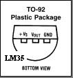
- Diode-temperature sensor
LM35 from National in TO-92
plastic package.
- ADC 0831 as a
analog-digital converter, 8 pin DIP, 8
bits resolution.
I have
used as software.... - BASCOM-AVR compiler (standard version 1.0.0.9.c)
- A lot of help from Mark
Alberts (Thank you, Mark!)
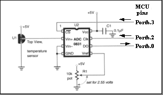
 The
temperature sensor, the ADC and pins from 2313 are wired as shown in the
figure:
The temperature sensor has a range from -55 to 150 şC, with an output of 10
mV per şC. If we measure with a tester the voltage between VOUT
and GND, will have 0,25 V for 25 şC and so on.
The
ADC0831 has a synchronous serial interface
Microwire from National semiconductors, which needs 3 wires for sending the
digital signals: CS (CS=0: chip select), CLK and Do.
Do
(8-bits) will range from 0 to 255, so if we set the reference voltage Vref
at 2,55 V for the 0831, we will have a digital measuring range from 0 to 255
ş C for the output, as we measure at 10 mV/şC with a minimum resolution of 1 şC at the ADC output. Of course there
are another limits, as the maximum operating temperature of chip and
electronics circuits.
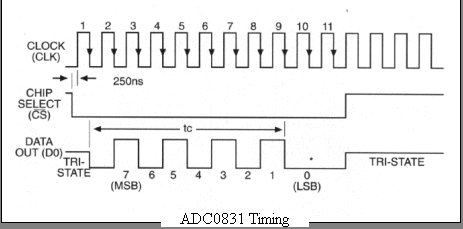
How it
works...
When
you select the chip (with CS = 0) from the MCU sending a low
by pinb.3, the ADC "wakes up", and it is ready to take a
measurement and output it one bit at a time through D0. The MCU controls this
process through the clock pinb.2. Each pulse of this clock indicates to the
ADC to place a bit on D0. The MCU grabs that bit, and adds it to a byte
variable in which it will accumulate all eight bits.
Of
course there are plenty of ways to do this kind of measures, but this one it
is very simple, and I think it is a good opportunity to start with BASCOM-AVR
compiler. Enjoy!
Here
is the code:
'aduc0831 example
Dim As Byte 'hold each bit coming from the ADC
Dim Temp As Byte 'each tick of the clock
Dim T As Byte 'var that will hold result
Config portb = &B11111110'pinb.0 as input; b.1..b.7 as
' output
Clk Alias Portb.2
Cs Alias Portb.3
Set cs 'begin with high
Do
Reset Clk
Reset Cs 'select chip
Gosub Pulse
Gosub Pulse 'extra clock for sync
A = 0 : T = 0
For Temp = 1 To 8 'start a new measure
T = T * 2 'send the bit (i) one place to left
Gosub Pulse 'send a clock pulse
T = T + A 'grab the last bit
If Pinb.0 = 1 Then 'read a new bit
A = 1
Else
A = 0
End If
Next
Set Cs
Print T
Wait 1
Loop
End
Pulse:
Set clk
Waitus 10 ' 10 us wait
Reset Clk
Return
|