|
|
| |
|
|
| |
|
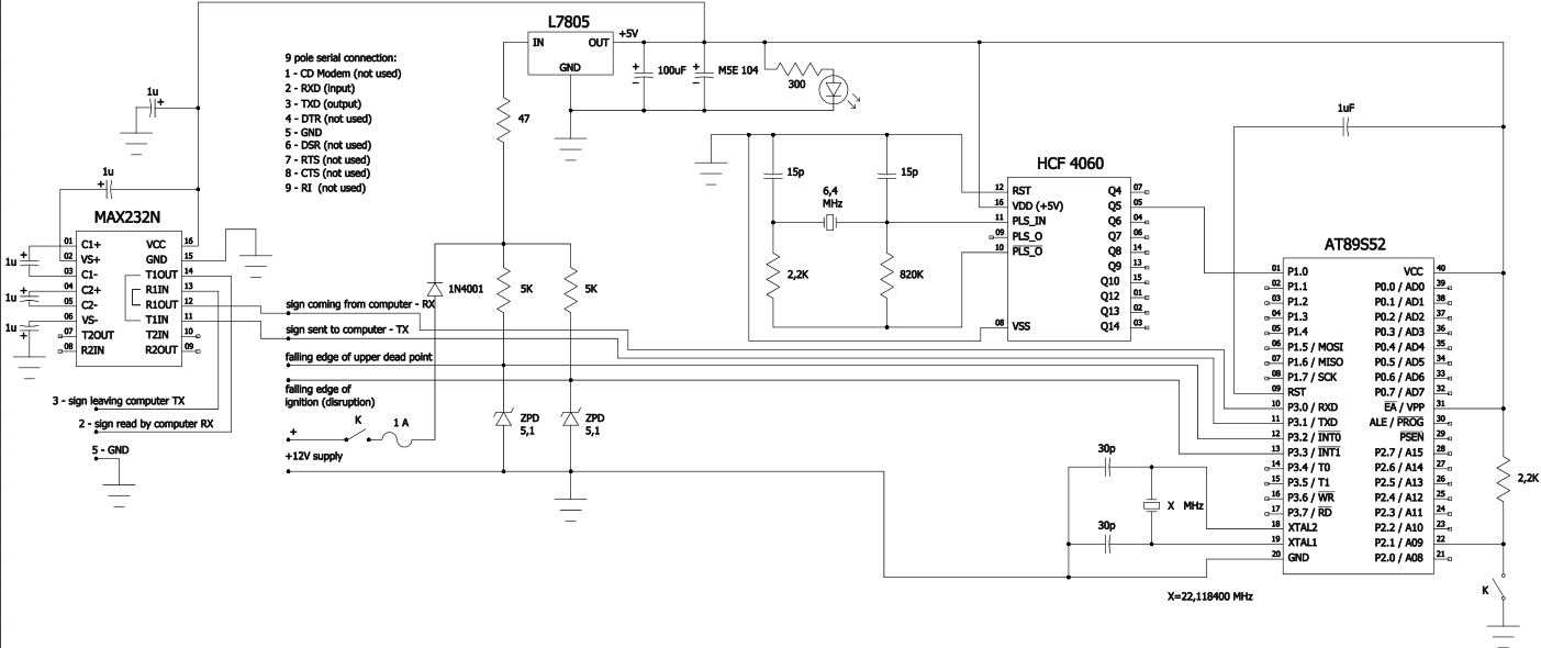
AN #44 - Ignition angle measuring device for two stroke internal combustion engine |

|
Measuring device for testing electronic ignition control on two stroke engines in real time.
This measuring device was made for testing electronic ignition control for two stroke engines in real time. The electronic circuit of it is the result of a minimal modification of a circuit designed for ignition control. I think it can be further simplified regarding the external clock working at 200KHz and providing sign for port P1.0 as well as the size of microcontroller (AT89s52), but this was not the aim of the project.
The device receives - as inputs - interrupt at the upper dead point of the revolving crankshaft and at the point of ignition. Between these interrupts the device measures, by polling, the time, and, by using serial communication, it sends the data to a computer for further processing. I used serial/USB converter for a laptop not having serial communication port and it worked well with it.
I tested my ignition control program with this measuring device using the sweep function of a waveform generator starting from 3Hz (180 rev/minute) and running as far as 100Hz (6000 revolution/minute) during 500 sec running time. A real testing during driving a car can also be done as well.
The corresponding program of the computer (not provided) receives the time data in real time in form of synchronized dual packages and places it alongside the corresponding angular speed of the crankshaft in an excel table (for example at right of the reference column to the spectrum of angular speeds - in my case having an interval or step of 10 rev/minute). Overwriting happens. The ignition angle (max and min value) to a certain angular speed of the crankshaft then can easily be calculated using the time data and taking into account the number of engine cylinders during the calculation.
Mr. Zsolt FAZEKAS (fazekaszs@hotmail.com)
Schematic:
Source code:
'--------------------------------------------------------------------------------------
' real time measurement of preignition angle for two stroke engine
' made by Zsolt Fazekas (fazekaszs at hotmail.com)
' Copyright reserved
'--------------------------------------------------------------------------------------

$regfile = "89s52.dat"
$crystal = 22118400
$map
$baud = 19200

Dim E As Word                                                 'time elapsed from interruption until upper dead point
Dim F As Word                                                 'time elapsed from upper dead point until interruption
Dim K As Byte                                                 'secondary variable counting the number of measures made by timer2

Dim Fh As Byte                                                'Fh, Fl, Eh, El - upper and lower bytes of F and E
Dim Fl As Byte
Dim Eh As Byte
Dim El As Byte

Reset F
Reset E
Reset K

Reset Fh
Reset Fl
Reset Eh
Reset El

Set Tcon.0                                                    'INT0 falling edge
Set Tcon.2                                                    'INT1 falling edge

Enable Interrupts
Enable Timer2
Enable Timer1
Disable Serial


Config Timer2 = Counter , Gate = Internal , Mode = 0          'not the capture mode, however simple counter mode
Counter2 = 0                                                  'reset counter (driven by a 200KHz outside clock sign coming in through port P1.0)

Config Timer1 = Timer , Gate = Internal , Mode = 2            'auto reload for transmit
Load Timer1 , 3

Declare Sub Kuld(f As Word , E As Word , Fh As Byte , Fl As Byte , Eh As Byte , El As Byte)

On Int0 Fordulatszam                                          'falling edge interrupt coming in through port P3.2 (at upper dead point)
On Int1 Elogyujtas                                            'falling edge interrupt coming in through port P3.3 (at the point of ignition)

Start Timer1
Start Timer2


Do
Enable Int0
Enable Int1
Loop
End

Fordulatszam:                                                 'INT0 interrupt, saving E
Stop Timer2                                                   'stop timer 2 for reading
Reset Tcon.1                                                  'deleting the interrupt flag
K = K + 1

If T2con.7 = 1 Then                                           'overflow flag is 1, (f. e. because crankshaft halts)
Counter2 = 0
Reset T2con.7                                                 'overflow flag is deleted
Start Timer2
F = 0
E = 0
K = 0
Else
   Eh = Th2
   El = Tl2
   E = Makeint(el , Eh)
         If K >= 3 Then                                       'after enabling interrupt one has to wait until K=3
         Disable Int0
         Disable Int1
         Call Kuld
         K = 0                                                'the value of K is reset after serial transmission
         End If
   Counter2 = 0
   Start Timer2
End If
Return


Sub Kuld(f As Word , E As Word , Fh As Byte , Fl As Byte , Eh As Byte , El As Byte)
F = F + 6                                                     '6 and 4: time ellapsing between stopping and starting Timer2
E = E + 4                                                     'this should be added to times measured for correction
Fh = High(f)
Fl = Low(f)
Eh = High(e)
El = Low(e)
If Fl = 255 And Fh = 255 Then                                 'the higest value should be avoided because of sincronisation
Fl = 254
End If
If El = 255 And Eh = 255 Then                                 'the higest value should be avouded because of sincronisation
El = 254
End If
If P2.1 = 1 Then                                              'switch
Scon = &H40
Enable Serial
Sbuf = 255                                                    'for sincronisation
Bitwait Scon.1 , Set
Reset Scon.1
Sbuf = 255                                                    'for sincronisation
Bitwait Scon.1 , Set
Reset Scon.1
Sbuf = Fl
Bitwait Scon.1 , Set
Reset Scon.1
Sbuf = Fh
Bitwait Scon.1 , Set
Reset Scon.1
Sbuf = El
Bitwait Scon.1 , Set
Reset Scon.1
Sbuf = Eh
Bitwait Scon.1 , Set
Reset Scon.1
Disable Serial
End If
End Sub


Elogyujtas:                                                   'INT1 interrupt, saving F
Stop Timer2                                                   'stop timer 2 for reading
Reset Tcon.3                                                  'deleting the interrupt flag
K = K + 1

If T2con.7 = 1 Then                                           'overflow flag is 1, (f. e. because crankshaft halts)
Counter2 = 0
Reset T2con.7                                                 'overflow flag is deleted
Start Timer2
K = 0
E = 0
F = 0
Else
      Fh = Th2
      Fl = Tl2
      F = Makeint(fl , Fh)
      Counter2 = 0
      Start Timer2
End If
Return |
|
|
| |
|
|
|