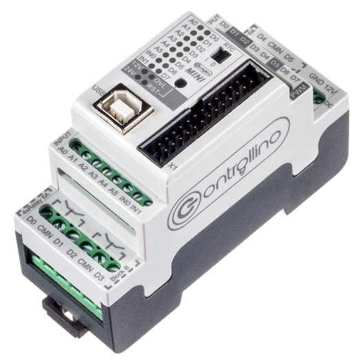
The Controllino Mini is an industry-standard Arduino application. It is based on the Arduino UNO board.
The Controllino Mini is an industry-standard Arduino application. It is based on the Arduino UNO board. There are all functionalities of the Uno Board available, inputs and outputs works with 12V / 24V levels. The housing can be mounted on a rail.
Manufacturer is the company Conelcom GmbH based in Austria. www.controllino.biz
The Controllino Mini is equipped with the following features:
Microcontroller: ATmega328
Atmel Clock Speed: 16 MHz
RTC
1x serial Interface
1x SPI Interface
1x I2C Interface
Input current Max. 8A
6x Relays Outputs 230V / 6A
8x Analog/Digital Inputs 12V or 24V
8x Digital Outputs 2A @12V or 24V
3x PWM Outputs
Usually the Controllino is programmed via the Arduino IDE.
The following example explains the programming of the Controllino with BASCOM.
The program shows the following functions of the Controllino:
Set and start the Real Time Clock
Retrieving and displaying the date and time
Text output via the serial interface
The digital inputs A0 - A3 control the digital outputs / Relias D0 - D3
Analogue measurement at the inputs A4 u. A5
Interrupts via inputs IN0 u. IN1
Signal output at the outputs D6 a. D7
PWM signal to output D5
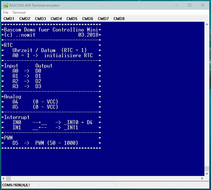
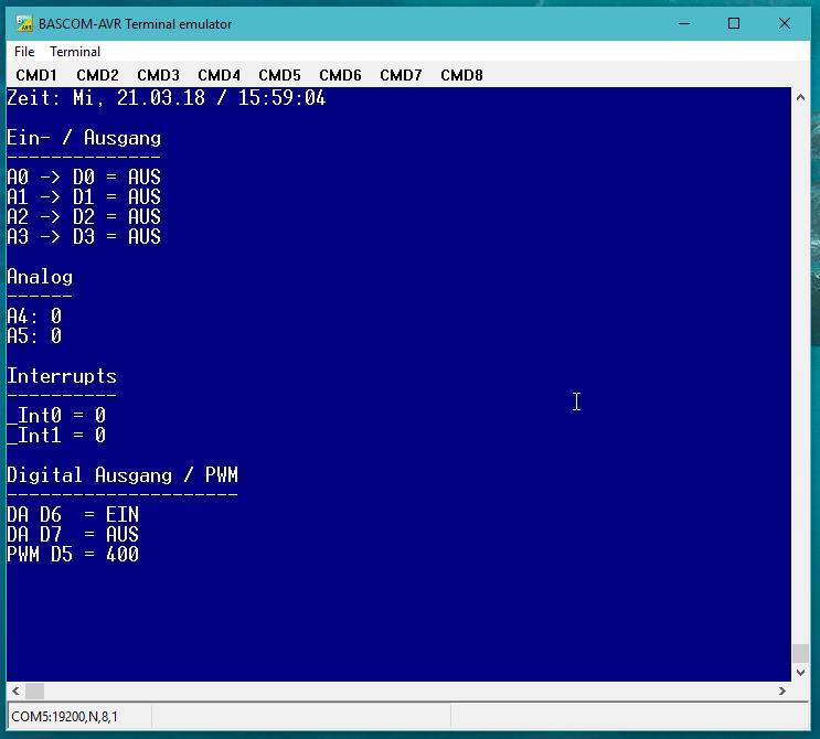
The BASCOM Terminal Emulator displays all program actions.
The serial communication is set to a baud rate of 19200 baud.
Two "screens" are displayed. To one the functions and to the other the actual actions.
Programming the Controllino can be done via the already loaded boot loader. AVRDUDE should be used for this.
http://savannah.nongnu.org/projects/avrdude
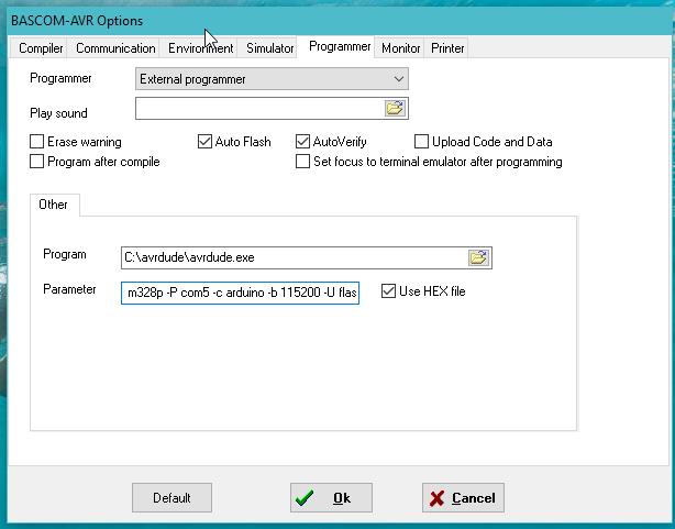
In this case, the following settings should be made in the BASCOM option:
Option Programmer
Programmer : External Programmer
Program: Path to avrdude.exe
Parameter: -C c:\avrdude\avrdude.conf -p m328p -P com5 -c arduino -b 115200 -U flash:w:{FILE}:i
Source code:
'###############################################################################
'BASCOM Demo Controllino MINI
'
'Entspricht Arduino Uno
'Prozessor: ATMega328 - 32 TQFP
'
' (c) by .:nomit - Nordhorner Mikrocontroller Technik 03.2018
'-------------------------------------------------------------------------------
' --- Ports , Pin Belegung ---
' µc Ports Controllino Funktion Leiste X1
'-------------------------------------------------------------------------------
' Port B:
' 0 D4 / Relay D4 OUT 16
' 1 D5 / Relay D5 / PWM OC1A OUT 17
' 2 SS RTC RTC 20
' 3 MOSI RTC 21
' 4 MISO RTC 22
' 5 SCK RTC 23
' 6 OSC
' 7 OSC
'
' Port C
' 0 A0 IN / ADC0 3
' 1 A1 IN / ADC1 4
' 2 A2 IN / ADC2 5
' 3 A3 IN / ADC3 6
' 4 D6 / SDA OUT / I2C BUS 18
' 5 D7 / SCL OUT / I2C BUS 19
' 6 RESET Reset 11
'
' Port D
' 0 RxD COM 26
' 1 TxD COM 25
' 2 IN0 IN / Interrupt 0 9
' 3 IN1 IN / Interrupt 1 10
' 4 D0 / Relay D0 OUT 12
' 5 D1 / Relay D1 / PWM OC0B OUT 13
' 6 D2 / Relay D2 / PWM OC1B OUT 14
' 7 D3 / Relay D3 OUT 15
'
' ADC6 A4 ADC6 7
' ADC7 A5 ADC7 8
'
' 5V+ 1
' GND 2
' 3.3V+ 24
'###############################################################################
$regfile = "m328pdef.dat" 'als 32 TQFP
$framesize = 32
$swstack = 32
$hwstack = 64
$crystal = 16000000 'Resonatorfrequenz
$baud = 19200 'Baudrate (Übertragungsgeschwindigkeit)
Baud = 19200
'##### Variablen Uhrzeit ######
Dim Stunden As Byte
Dim Minuten As Byte
Dim Sekunden As Byte
Dim Tag As Byte
Dim Wochentag As Byte
Dim Monat As Byte
Dim Jahr As Byte
Dim Txt_rtc As String * 25 'String für Zeit
'##### Variablen #######
Dim Zur_rtc(10) As Byte 'für SPI / RTC
Dim Von_rtc(10) As Byte 'für SPI / RTC
Dim Result As Word 'ADC Ergebnis
Dim _int0 As Byte 'Zähler Interrupt In0
Dim _int1 As Byte 'Zähler Interrupt In1
Dim X As Byte 'Allgemein
Dim Status(2) As String * 3 'Statusmeldung für Ein- / Ausgänge
Status(1) = "AUS"
Status(2) = "EIN"
'##### Variabel PWM #####
Dim _pwm As Word 'Zähler PWM
Dim _pwm_rauf As Bit 'Flag für PWM rauf / runter
'##### Alias der Controllino Ports #####
D0 Alias Portd.4 'Digital Ausgänge D0 - D7
D1 Alias Portd.5
D2 Alias Portd.6
D3 Alias Portd.7
D4 Alias Portb.0
D5 Alias Portb.1
D6 Alias Portc.4
D7 Alias Portc.5
A0 Alias Pinc.0 'Digital Input
A1 Alias Pinc.1
A2 Alias Pinc.2
A3 Alias Pinc.3
In0 Alias Pind.2 'Eingänge A4 u. A5 als Digital Eingang
In1 Alias Pind.3
Const Adc_a0 = 0 'Analog Kanäle A0 - A5
Const Adc_a1 = 1
Const Adc_a2 = 2
Const Adc_a3 = 3
Const Adc_a4 = 6
Const Adc_a5 = 7
'#### Alias des SPI Bus ####
Rtc_ss Alias Portb.2
Mosi Alias Portb.3
Miso Alias Pinb.4
Sck Alias Portb.5
'##### Delcare Subs ######
Declare Sub Rtc_schreiben(byval Tt As Byte , Byval Mm As Byte , Byval Jj As Byte , Byval Wt As Byte , Byval H As Byte , Byval M As Byte , Byval S As Byte )
Declare Sub Rtc_lesen()
Declare Sub Rtc_reset()
'##### RTC Register #####
Const Rtc_control_1 = &H00
Const Rtc_control_2 = &H01
Const Rtc_seconds = &H02
Const Rtc_minutes = &H03
Const Rtc_hours = &H04
Const Rtc_days = &H05
Const Rtc_weekdays = &H06
Const Rtc_months = &H07
Const Rtc_years = &H08
'-------------------------------------------------------------------------------
'Programm : Main
'Funktion : Hauptroutine
'Aufruf von : Reset
'Ausgabe : ---
'Eingabe : ---
'Bemerkung :
'-------------------------------------------------------------------------------
Main:
'Ports
Ddrb = &B11111111 'PortB als Ausgang
Portb = &B00000000 'Alles aus
Ddrc = &B01110000 'D4 + D5 = Ausgang, A0 - A4 = Eingang
Portc = &B11000000 'Relais aus, A0 - A4 Pullup aus !
Ddrd = &B11110011 'PortD 4 - 7 ,0-1 als Ausgang , IN0 u. IN1 als Eingang
Portd = &B00000011 'D4 - D7 aus, IN0 u. IN1 Pullup aus !
'SPI RTC
Config Spi = Hard , Interrupt = Off , Data_order = Msb , Master = Yes , Polarity = Low , Phase = 0 , Clockrate = 4 , Noss = 1
Spiinit
'AD Konverter
Config Adc = Single , Prescaler = Auto , Reference = Avcc
'PWM
Config Timer1 = Pwm , Pwm = 10 , Compare A Pwm = Clear Up , Prescale = 8 '980Hz
Set _pwm_rauf 'Richtung rauf zählen
_pwm = 0 'Vorbesetzen
Pwm1a = _pwm
'Interrupts
On Int0 Int0_isr 'Interrupt Serviceroutine
Config Int0 = Falling 'Auslösen durch fallende Flanke
Enable Int0 'Interrupt freibegeb
On Int1 Int1_isr 'Interrupt Serviceroutine
Config Int1 = Rising 'Auslösen durch steigende Flanke
Enable Int1 'Interrupt freibegeb
Enable Interrupts 'alle Interrupts freigeben
Set D6 'Ausgang vorbesetzen
Reset D7 'Ausgang vorbesetzen
'Ende der Initialisierung
Print
Print "***********************************"
Print "*Bascom Demo fuer Controllino Mini*"
Print "*(c) .:nomit 03.2018*"
Print "*---------------------------------*"
Print "*RTC *"
Print "* Uhrzeit / Datum (RTC = 1) *"
Print "* A0 = 1 -> initialisiere RTC *"
Print "*---------------------------------*"
Print "*Input Output *"
Print "* A0 -> D0 *"
Print "* A1 -> D1 *"
Print "* A2 -> D2 *"
Print "* A3 -> D3 *"
Print "*---------------------------------*"
Print "*Analog *"
Print "* A4 (0 - VCC) *"
Print "* A5 (0 - VCC) *"
Print "*---------------------------------*"
Print "*Interrupt *"
Print "* IN0 --+__ -> _INT0 + D4 *"
Print "* IN1 __+-- -> _INT1 *"
Print "*---------------------------------*"
Print "*PWM *"
Print "* D5 -> PWM (50 - 1000) *"
Print "***********************************";
Wait 5
Print
Call Rtc_reset
'Initialisieren der RTC nach Reset, wenn Eingang A0 = high Level ist
If A0 = 1 Then 'A0 = High, schreibe Uhrzeit / Datum neu
Call Rtc_schreiben(19 , 3 , 18 , 1 , 09 , 58 , 30) 'setzte RTC auf: Mo, 19.03.18 / 09:58:30
Print "RTC wurde neu initialisiert..."
Wait 2
End If
Do
'Demo RTC
Call Rtc_lesen()
Print "Zeit: " ; Txt_rtc
'Demo Digital Input / Output
D0 = A0 'Ausgänge schalten
D1 = A1
D2 = A2
D3 = A3
Print
Print "Ein- / Ausgang"
Print "--------------"
X = A0 + 1
Print "A0 -> D0 = " ; Status(x)
X = A1 + 1
Print "A1 -> D1 = " ; Status(x)
X = A2 + 1
Print "A2 -> D2 = " ; Status(x)
X = A3 + 1
Print "A3 -> D3 = " ; Status(x)
'Demo ADC
Print
Print "Analog"
Print "------"
Result = Getadc(adc_a4) 'Analog A4
Print "A4: " ; Result
Result = Getadc(adc_a5) 'Analog A5
Print "A5: " ; Result
'Demo Interrupt
Print
Print "Interrupts"
Print "----------"
Print "_Int0 = " ; _int0
Print "_Int1 = " ; _int1
'Demo Digital Ausgang ohne Relais
Toggle D6
Toggle D7
Print
Print "Digital Ausgang / PWM"
Print "---------------------"
X = D6 + 1
Print "DA D6 = " ; Status(x)
X = D7 + 1
Print "DA D7 = " ; Status(x)
'Demo PWM
If _pwm_rauf = 1 Then 'welche Richtung wird gezählt?
If _pwm < 1000 Then
_pwm = _pwm + 50
Else
_pwm = _pwm - 50
Reset _pwm_rauf 'Runter zählen
End If
Else
If _pwm > 50 Then
_pwm = _pwm - 50
Else
_pwm = _pwm + 50
Set _pwm_rauf 'Rauf zählen
End If
End If
Pwm1a = _pwm 'PMW1A stetzen
Print "PWM D5 = " ; _pwm
Wait 1
Loop
End
'-------------------------------------------------------------------------------
'Subroutine : RTC_Reset
'Funktion : Software Reset RTC
'Aufruf von : Main
'Ausgabe :
'Eingabe :
'Bermerkung :
'-------------------------------------------------------------------------------
Sub Rtc_reset()
Rtc_ss = 1 'Chipselect ein
Zur_rtc(1) = &H10
Zur_rtc(2) = &H58
Spiout Zur_rtc(1) , 2
Rtc_ss = 0
End Sub
'-------------------------------------------------------------------------------
'Subroutine : RTC_Lesen
'Funktion : Lese Uhrzeit und Datum
'Aufruf von : Main
'Ausgabe : Tag, Monat, Jahr , Wochentag, Stunden, Minuten, Jahr , txt_RTC
'Eingabe :
'Bemerkung : Ausgabe in Dezimalwerte, String
'-------------------------------------------------------------------------------
Sub Rtc_lesen()
Zur_rtc(1) = &H92 'Lese von Adresse 02h
Rtc_ss = 1 'Chipselect ein
Von_rtc(1) = Spimove(zur_rtc(1) , 8)
Rtc_ss = 0
Von_rtc(2) = Von_rtc(2) And &B01111111 'Reset Wert filtern
Von_rtc(3) = Von_rtc(3) And &B01111111 'Reset Wert filtern
Sekunden = Makedec(von_rtc(2)) 'Sekunden umwandeln in Dezimal
Minuten = Makedec(von_rtc(3)) 'Minuten umwandeln in Dezimal
Stunden = Makedec(von_rtc(4)) 'Stunden umwandeln in Dezimalin
Tag = Makedec(von_rtc(5)) 'Wochentag umwandeln in Dezimalin
Wochentag = Makedec(von_rtc(6)) 'Tag Umwandeln In Dezimalin
Monat = Makedec(von_rtc(7)) 'Monat umwandeln in Dezimalin
Jahr = Makedec(von_rtc(8)) 'Jahr umwandeln in Dezimalin
Select Case Wochentag 'Suche Wochentag
Case 00
Txt_rtc = "So, "
Case 01
Txt_rtc = "Mo, "
Case 02
Txt_rtc = "Di, "
Case 03
Txt_rtc = "Mi, "
Case 04
Txt_rtc = "Do, "
Case 05
Txt_rtc = "Fr, "
Case 06
Txt_rtc = "Sa, "
End Select
Txt_rtc = Txt_rtc + Bcd(von_rtc(5)) + "." + Bcd(von_rtc(7)) + "." + Bcd(von_rtc(8)) + " / " + Bcd(von_rtc(4)) + ":" + Bcd(von_rtc(3)) + ":" + Bcd(von_rtc(2))
End Sub
'-------------------------------------------------------------------------------
'Subroutine : RTC_schreiben
'Funktion : Schreibt Uhrzeit und Datum
'Aufruf von : Main
'Ausgabe :
'Eingabe : Tag(1-31), Monat(1-12), Jahr(0-165), Wochentag (0-7 (0=So,1=Mo,..), Stunde(0-23), Mintuen(0-59), Sekunden(0-59)
'Bemerkung : Eingabe in Dezimalwerte
'-------------------------------------------------------------------------------
Sub Rtc_schreiben(byval Tt As Byte , Byval Mm As Byte , Byval Jj As Byte , Byval Wt As Byte , Byval H As Byte , Byval M As Byte , Byval S As Byte )
Zur_rtc(1) = &H12 'Schreibebefehl ab Adresse 02h
Zur_rtc(2) = Makebcd(s) 'Sekunden in BCD
Zur_rtc(2) = Zur_rtc(2) And &H7F 'Ozilator aktiveren
Zur_rtc(3) = Makebcd(m) 'Minuten in BCD
Zur_rtc(4) = Makebcd(h) 'Stunden in BCD
Zur_rtc(5) = Makebcd(tt) 'Tag in BCD
Zur_rtc(6) = Makebcd(wt) 'Wochentag in BCD
Zur_rtc(7) = Makebcd(mm) 'Monat in BCD
Zur_rtc(8) = Makebcd(jj) 'Jahr in BCD
Set Rtc_ss 'Chip Select
Spiout Zur_rtc(1) , 8 'Schreibe Werte
Reset Rtc_ss
End Sub
'-------------------------------------------------------------------------------
'Subroutine : Int0_Isr
'Funktion : INT0 Interrupt Serviceroutine
'Aufruf von : IN0, fallende Flanke
'Ausgabe : Incr _Int0, Toggle D4
'Eingabe :
'Bemerkung : Kein Entprellen des Eingangs;
'-------------------------------------------------------------------------------
Int0_isr:
Incr _int0 'Zähler für In0
Toggle D4 'Relais setzen / löschen
Return
'-------------------------------------------------------------------------------
'Subroutine : Int1_Isr
'Funktion : INT1 Interrupt Serviceroutine
'Aufruf von : IN1, steigende Flanke
'Ausgabe : Incr _Int1
'Eingabe :
'Bemerkung : Kein Entprellen des Eingangs
'-------------------------------------------------------------------------------
Int1_isr:
Incr _int1 'Zähler für In1
Return
|