The following text is translated by Vasiliy, thanks!I
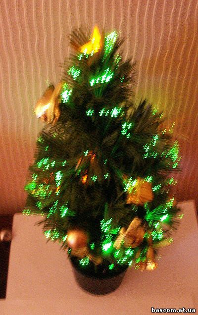
wanted to joy myself and my friends on New Years and I bought a synthetic Christmas
tree with an FO illumination IGT040EG1. The tree was 40 cm high and was powered by 3 AA batteries with total voltage 4,5 V. I switched the tree on in a
dark room and prepared to see a nice light show, but I was surprised
when the tree began to flash red and yellow in turn.
This synthetic wonder was
operated by a small board with a bun-like chip, which switched two bright LEDs
of red and yellow color in turn. Among the
tree branches there was a separate hanging garland made of LEDs of white color, which shined brightly by switching on the
tree. At the top of the tree was a transparent plastic star with some LEDs
inside. The star was electrically connected with the garland and was switched
on with it at the same time. This is strictly speaking all that I can say about
this original product of Chinese industry.
I
supposed that technical possibilities of the tree allow to reproduce more lighting
effects and I have worked out a control board on micro controller Atmega 8L-8,
which is mounted instead of the old one. In this new variant the tree creates
very beautiful light patterns and dynamic effects, it can work in 4 modes:
automatic, acoustic clap switch, acoustic-interactive, photo detector.
Here are
some of the realized lighting effects: fast switchings of three-colored LEDs
(for each color), lighting effect «shimmer» (for each color), color mixing,
fast switching on fluent switching off, consecutive switching of LEDs
crystals with an effect of light accumulation and changing, color impulses with
a small pause (for each color), increase of flash frequency, alternate
switching from tree to garland with glow color changing, etc. The use of bright
RGB-LEDs allows to watch lighting effects by the daylight, but the best results
turn out in a dark room or by the switched off overhead illumination.
The
garland situated on the tree shined too bright, so I had to limit programmatic the glow brightness level. For energy economy and for luminous
emittance leveling of the garland and the tree the garland operating occurs
with the impulse duration less than 50% from the initial. Besides, the garland
is switched on not in all program units but only in the last three. The garland
reproduces the following lighting effects: flashes, fast switching on fluent
switching off, switchings, shimmering.
Switching
from one mode to another is realized cyclic by the short pressure of the button
on the upper frame cover. The two-colored LED
(red-blue) placed near fulfills service options indicating active working mode.
An external interrupt at the microcontroller INT0 output is used for button
SB1 operating. Thats why button mode switching can be made at any moment.
In
the automatic mode the indicating LED is not shining, there is no need to push
the mode choice button. The automatic mode starts just after the power is
switched on (at the frame bottom) and then
reproduces cyclic programmed lighting effects. The mode changing is possible by
single short pressures of the button SB1. Control board reproduces cyclic 12
complicated program units, which create an original light pattern on the tree.
Every lighting effect is reproduced for each color, so the total amount is 36
effects. A single effect for every color is repeated many times, it also
increases the total amount of reproduced effects. The automatic mode is
convenient because it doesnt require efficient intervention; the program makes
everything creating different light patterns on the tree surface.
In
the acoustic mode «сlap
switch» the indicating LED HL1 shines continuously with red color. The mode is
switched on by one short pressure of the button SB1. The tree switches on only
after the third clap and it will continue to work autonomously reproducing
lighting effects. At the clap moment the indicating LED is going out for a
split second, it confirms the received sound signal. After the third clap all
following claps wont be effective. For restart the button SB1 should be pushed
3 times. This mode can be used at parties and holidays for attracting attention
and creating a mysterious atmosphere.
Switching
on the second acoustic mode «interactive»: the button SB1 should be pushed 2
times (if at the beginning) or once if the previous mode is changing. The
indicating LED will shine blue, and then its possible to start interactive
three-colored composite effect. The tree will respond to every sound signal
with fast successive reproducing of three colors: blue, red and green. The
sensitiveness to sound signals in this mode is very high and the device will
react even to human speech. The color symphony can play a role of an
accompaniment to karaoke songs or to music.
Switching
on the mode «photodetector»: the button SB1 should be pushed 3 times (if at the
beginning) or once if previous mode is changing. When the mode is switched on
the indicating LED HL1 will flash red. It means that the beginning of a
programmed test of the room illumination level. Thats why its recommended to
switch on this mode by the already turned on general illumination of the room.
The slightest darkening or turning the light off will lead to reproducing
programmed lighting effects. The specific of the mode «photodetector» is that
just the light in the room is turned on once again the lighting effect on the
tree switches off. The following turning-off the light in the room lights the
illumination on the tree again etc
The reason is that the phototransistor is
connected to the second microcontroller external interrupt INT1, which allows
to start or to stop efficiently the lighting effects program.
The
next pressure of the button SB1 switches the program into the first mode. In
order to prevent the bounce the stop in the interrupts are a bit more than
usual. It shows by sight as a rather late mode switching.
The
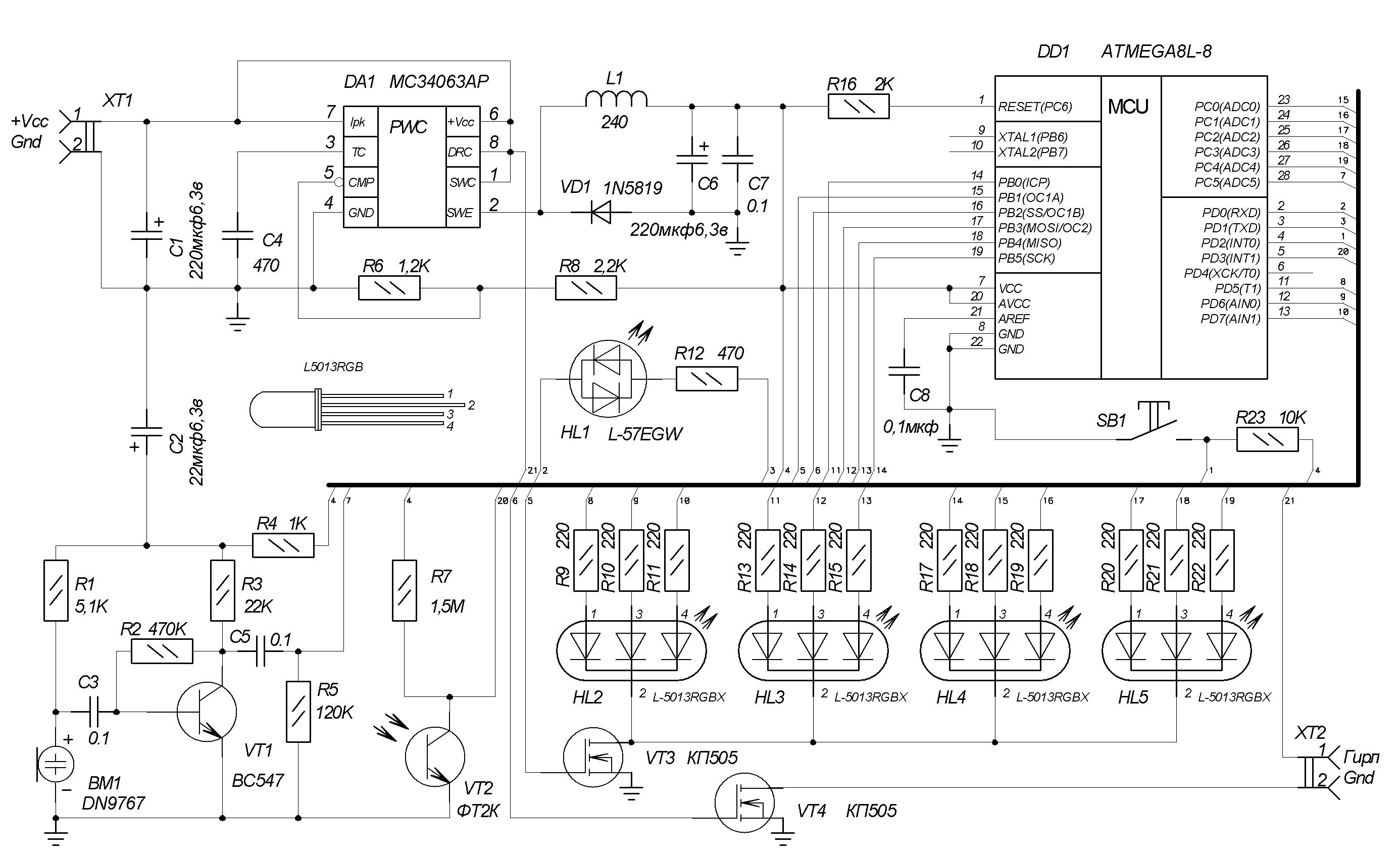
electric scheme is based on the microcontroller Atmega8L-8 with a minimal
supply voltage level ca. 2,7V. The choice of this microcontroller is caused by
the limit of supply voltage in form of a tree batteries set with common voltage
4,5V. To prolong the batteries operating life and to raise efficiency all
component parts are powered by a pulse-duration conversion device MC34063AP.
Out voltage 3,5V after resistors R6R8 comes to the microcontroller, indicating
LED HL1, three-colored LEDs HL2-HL5, note amplifier, and transistor VT1.
For
sound signals reception and analysis Ive built a low-frequency amplifier on
transistor VT1. Sound signal appears on the microphone port BM1 as weak electric
impulses. They come through the capacitor C3 and the transistor amplifiers
base where they have voltage amplification. Then the intensified sound signal
comes from the upper (due the scheme) resistor terminal R5 to the
microcontrollers port 28 ADC5 and is digitalized. Then the volume level and
the pause between signals are programmatic analyzed. For the second mode «clap
switching » the acoustic signal becomes considerably weaker and the pause
control between signals is used. On the contrary, for the mode «acoustic
interactive» the signal amplification is programmatic realized and the tree
can react to common human speech. The device sensibility to sound signal can be
changed not only programmatic but also by changing the resistance of the
resistor R5.
The
following is programmed in the microcontroller DD1 cell: the routines of
lighting effects reproducing and the signals of out sensors of photo transistor
VT2, button SB1 and amplifier output. The inner generator RC 4 MHz is hooked up
programmatically. The program is written on BASIC in BASCOM-AVR
software-envelope and is a bit more than 4Kb. To set fuse bits by programming
is not needed. Resistor R16 disables an inadvertent trip-out by voltage
reduction in the feed network.
Crystal operating of each HL2-HL5
LEDs is organized due the program. In order to create a great variety of
effects all cathodes are hooked up through the FET VT1, which functions in
pulse-time modulation mode. This signal comes from the OC1A port and allows
turning all three-colored LEDs on and off fluent. The garland on the tree is
operated by the same way. Its operated by the global bus which is hooked up
through the FET VT4. The operating signal comes from the microcontroller to FET
VT4. The impulse duration in the signal is changed due the given program. It
shows in different lighting effects on the garland. The microcontroller not
only operates RGB-LEDs but also combines their switching on with the
LED-garland. As a result there are composite lighting effects.
Parts
and materials
The
printed-circuit board (dr.2) is made from a single-sided glass-fiber laminate
sheet with thickness 1,5-2 mm. The dimensions are 60,2x60,2 mm. Radio elements
are mounted due the dr. 3. The list of radio elements you can see in the table1.
The shape of the printed-circuit board has a figured notch where plastic pin
for a screw should be placed after the installation of the board in the frame.
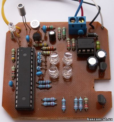
Please
pay attention to phototransistor VT2, two-colored LED HL1 and button SB1
setting. They are mounted after all radio parts. You need to prepare 2 holes
for phototransistor and LED on the upper frame cover beforehand. By the
mounting of phototransistor and LED the length of legs should be so that the
upper cover can close free and the frames of the details slightly outlook from
the holes.
After
marking-off you need to make two holes on the upper cover for the button
setting (see the photo). The diameter of the holes is ca. 1 mm. The button pins are passed through the holes and are incurved from the opposite side. The
button is connected with the board with 2 bounding wires. Theres no need to
make special holes for the microphone, the high sensibility of the scheme
allows receiving sound signals in close frame.
Here
can be used any 3 mm two-colored LED of red and blue colors.
List
of radio parts
|
Position
|
Name
|
Comment
|
Quantity, pcs
|
|
DD1
|
Altmega8L-8
|
Replacement is not recommended!
|
1
|
|
DA1
|
MC34063AP
|
|
1
|
|
VT1
|
BC547
|
|
1
|
|
VT2
|
ФТ-2К
|
phototransistor
|
1
|
|
VT3,VT4
|
КП505А
|
BS170P
|
2
|
|
R1
|
5,1 kO
|
0,125W
|
1
|
|
R2
|
470kO
|
0,125W
|
1
|
|
R3
|
22kO
|
0,125W
|
1
|
|
R4
|
1 kO
|
0,125W
|
1
|
|
R5
|
120 kO
|
0,125W
|
1
|
|
R6
|
1,2 kO
|
0,125W
|
1
|
|
R7
|
1,5 mO
|
0,125W
|
1
|
|
R8
|
2,2 kO
|
0,125W
|
1
|
|
R9-R11,R13-R15,R17-R22
|
220 О
|
0,125W
|
12
|
|
R12
|
470 О
|
0,125W
|
1
|
|
R16
|
2 kO
|
0,125W
|
1
|
|
BM1
|
DN9767
|
Electret small microphone
|
1
|
|
C1,C6
|
220uF10V
|
|
2
|
|
C2
|
22uF6,3V
|
|
1
|
|
C3,C5,C7,C8
|
0,1uF
|
|
4
|
|
C4
|
470picofarad
|
|
1
|
|
L1
|
240uH
|
|
1
|
|
VD1
|
1N5819
|
|
1
|
|
HL1
|
L57EGW or analogue
|
|
1
|
|
HL2-HL5
|
L5013RGB
|
|
4
|
|
SB1
|
Two-pin- button
|
|
1
|
|
XT1
|
Two-sectional - joint
|
|
1
|
|
-
|
Panel for microcontroller
|
DIP28pin
|
1
|


