Introduction
Atmel has recently released the new (blue) Xmega
A1 Xplain board and plug on sensors ATAVRSBIN1 (Inertial One) and ATAVRSBPR1
(Pressure One). This application note shows how to use Bascom to read the sensors
and to translate the raw data into Euler angles (yaw, pitch, roll) and
altitude above sea level. For Arduino users it is shown, how to make use of HEX
files generated by Bascom. Due to a rather competitive pricing of Xplain boards
and sensors, they are expected to find direct utilization in DIY-projects: RC-multicopter
flight controls, autopilots and flight stabilization systems in RC-planes,
camera stabilization systems, 3D game controllers, and pointing devices.
Background
AHRS refers to an Attitude and Heading
Reference System which is based on an Inertial Motion Unit (IMU). As explained
in a previous application note (AN #177 - Kixrazor Bascomers Electronic
Flight Information System for Sparkfuns 9DOF Razor: http://www.mcselec.com/index.php?option=com_content&task=view&id=269), sensor fusion is needed to convert the IMUs raw data into
meaningful information such as the Euler angles which describe the orientation
in 3D space. Custom designed IMU-boards combine a 3D-MEMS-gyroscope (here
Invensense ITG-3200), a 3D-MEMS-accelerometer (here Bosch BMA150) and a
3D-MEMS-magnetometer (here Asahi Kasai AK8975, used in Apples iPhone4). More
recently, such boards also contain a pressure sensor (here Bosch BMA 150), as
it is common experience that a GPS derived altitude is oftenly less accurate
and delayed compared to a pressure-derived altitude. Several algorithms exist
for the calculation of Euler angles from IMU raw data. The simplest utilizes so
called complementary filters (CF) in which accelerometer information and gyro
information is mixed to compensate for gyro drift and to obtain the Euler
angles by simple trigonometric calculations. CF (e.g. employed in the popular
MultiWiiCopter) are oftenly found sufficient to stabilize hovering, they are
rather fast and allow for a rapid update of brushless motor controllers. They
may however cause serious problems when asking for flight stabilization from
aerobatic maneuvers. The classical Kalman filters (KF) have advantages here,
however the procedure itself is computationally quite demanding heavily based
on matrix algebra (see AN #176 - Mini Matrix Algebra (http://www.mcselec.com/index.php?option=com_content&task=view&id=267&Itemid=57) ). Rather little matrix algebra is involved in an algorithm called
Direction Cosine Matrix (DCM) which combines a good estimation of Euler angles
(just 3 states of a KF) with the speed advantage of CF. More information on DCM
is found in a web-document written by Bill Premerlani and Paul Bizard (Direction
Cosine Matrix IMU: Theory, http://code.google.com/p/gentlenav/downloads/detail?name=DCMDraft2.pdf&can=2&q )
DCM is the method of choice also in this
Application Note. What was possible on the SFE Razor board at 50Hz a year ago,
both with Bascom and Arduino code, is now possible at almost 250 Hz and lower
cost, albeit momentarily available to Arduino users only as HEX code. Note that
this speed which multicopter developers may find useful enough is not the
end of the flag. As the core DCM without sensor reads and a little printing
runs at 800 Hz using Bascom (and could run even faster when making use of fixed
point math instead of floating point math) the 250 Hz achieved is due to
digital filtering on Invensense gyros (IMU 3000 included). Thus an Android
phone app which might be viewed as the alternative to the Atmel Xplained-based
approach, will also feel the 256 Hz limitation burned into the non-analog gyros
of Invensense. One does not need to see this as a disadvantage, however.
Digital on chip filtering has clear advantages when it comes to electric noise
and noisy environments such as on a multicopter.
What one needs to do for a start?
(1) The Xmega A1 Xplained board and the Sensors Xplained Inertial ONE
and Pressure ONE are available from a number of dealers, including Atmel
Store. Plug them together as shown below:
(2) Download AVR1927: XMEGA-A1 Xplained Getting Started Guide (http://atmel.com/dyn/resources/prod_documents/doc8372.pdf )
(3) Goto http://www.atmel.com/dyn/products/tools_card.asp?tool_id=17168&category_id=163&family_id=607&subfamily_id=1965 , and find software to download as two CD icons. In one case you
need to register at Atmel. Click the icons to download. I decided to place XMEGA-A1
Xplained Example Applications and USB driver and/or Xplained USB CDC Driver
into subfolders of Bascom-AVR.
(4) Goto http://atmel.com/dyn/products/tools_card.asp?tool_id=3886
and download Atmels FLIP programmer. Bascom and Arduino users may select FLIP
3.4.2. Click on the CD icon to start downloading. You will be asked to install
the Java runtime environment if it is not installed on your Windows PC so far.
(5) Before clicking FLIP_Installer_3.4.2, Bascom users are asked to read
Bascom HELP about FLIP. Have BASCOM 2.0.5.0 or later installed! Search by index
for FLIP and follow instructions. Arduino users without a copy of Bascom may
start installation of FLIP directly. Bascom users may do this also but on the
long run it is time-saving to use the FLIP-support build into the Bascom IDE.
(6) FLIP 3.4.2 misses the configuration file for the Xmega A1 Xplained
board. Follow AVR1927 (Chapter 5) where to find it. Briefly: The file ATxmega128A1.xml
needs to be copied into ..\Atmel\Flip 3.4.2\bin\PartDescriptionFiles.
(7) Follow AVR1927, chapter 5, how to set up a virtual comm port for
your Xmega A1 Xplained board.
(8) AVR1927, Chapter 5, recommends to use Batchisp for the bootloading
of Hex-Files. Bascom and FLIP are easier to use, however. Bascom users simply
select FLIP as the programmer, load the kiXAHRS_ONE.BAS file, and compile.
Before Send to chip from Bascom, the SW0-switch of the Xplained A1 board
needs to be pressed while plugging in the USB cable.
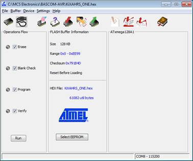
(9) Arduino users may start FLIP instead. Press SW0 on the Xplained
board and hold it while connecting board and PC using USB cable. From the menu:
File->Load Hex file->kiXAHRS_ONE.HEX. Click the button showing a USB
cable. Select RS232 for programming via USB virtual comm port. Connect the port
from the menu which pops up, and press RUN. The standard baud rate is 115200,
8N1. Dont forget to close FLIP after bootloading completion.
Testing kiXAHRS_ONE using a terminal
program
Bascom users have a terminal emulator
integrated in the IDE. This is also available in the free demo copy of Bascom
2.0.5.0. Plug in the kiXAHRS_ONE combo. LED1 flashes rapidly while the combo
measures the magnitude of gravity in accelerometer units. Right after, a stream
of data starts to scroll:
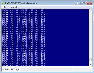
The first three numbers are the Euler
angles roll (X), pitch (Y) and yaw (Z). The roll axis is the one which connects
both boards (pointing to the pressure sensor), the pitch axis seperates them
while pointing to the top side (USB) and the yaw axis is perpendicular to the
board pointing downwards. The last three numbers indicate altitude above sea
level in meter, gyro temperature (under a lamp) in degree Celsius and looptime
in microseconds. There are two phases of data streaming. In the first 30
seconds the data show larger variations (phase I) reflecting an alternative to
"analog offsetting" previously discussed on the Diydrones forum. (http://diydrones.com/forum/topics/why-analog-offsetting-in-dcm?xg_source=activity ). After omega_I filling the combo switches to phase II
automatically - phase II has smaller Kp's and Ki's than phase I - the data are
smoother here.
Pressing SW7 on the board will show:
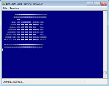
on a Bascom terminal (hoping that Bascom
may also pop up on a Atmel page;) and a second later there is a main menu:
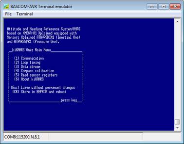
From here you can change baudrates,
looptimes, type of outstream,do magnetometer calibration, read I2C sensor
registers, and store your setting in EEPROM. Baudrates may range from 9600 bps
to 256000 bps with 115200 bps as the default. Selectable loop times range from
15000 microseconds
(default) to 4000 mics (250 Hz). Actual loop times are always a bit longer due
to I2C quanta. For example, the selection of 250 Hz will result in an average
of about 240 Hz, if one selects Just Hz as the outstream option. Data streaming
is possible in a number of formats including kixlines (http://www.mcselec.com/index.php?option=com_content&task=view&id=265&Itemid=57 ), SF9DOMAHRS based on Arduino code, the format shown a few
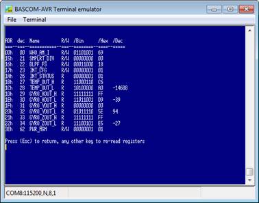
screenshots before, raw data display and just Hz. There is an option for
compass calibration in which you are asked to rotate the combo around all three
axes and bring it into as many different orientations as possible, and a
further option to read the I2C-registers of each of the 4 sensors in binary, hex,
and decimal formats. The following screenshot shows the registers of the
ITG-3200:
From the main menu, it is possible to store
all settings in EEPROM (just by pressing the Enter key (CR). This way it is
rather simple to fix the data stream to suit the need of a given application.
Planes, for example, need another loop timing than multicopters with high speed
brushless controllers.
Visualisation using AeroSimRC
AeroSimRC is a commercial (but affordable)
RC flight simulator of which a fully functional demo having a runtime
limitation of 2 min is downloadable from: http://www.aerosimrc.com/j/index.php/en/downloads . The simulator is a general purpose RC simulator, especially
suited for the training of FPV flight however. This is because AeroSimRC allows
to utilize rather easily satellite photographs from the flight area of your
choice. These data (e.g. from Google Maps) can be combined with digital
elevation data from NASAs SRTM mission which are available on public FTP
servers accessed by AeroSimRC.
I have written a plugin for AeroSimRC
(plugin_AeroSimRC.DLL) which allows to expand the capabilities of AeroSimRC for
three things:
(1) The safe testing of autopilot hardware on ground. This is done by
letting AeroSimRC stream GPS, altitude, attitude, heading, battery level to the
autopilot which then streams radio stick settings back to AeroSimRC. The
approach is called hardware in the loop simulation (HILS) and as all
streaming is in the kixline format, it is called kixHILS.
(2) The usage of AeroSimRC as a ground station during real flight. In
this mode the autopilot streams GPS, altitude, attitude, battery level, stick
settings to the ground via a telemetry connection. AeroSimRC then visualizes
these data as if they would result from a flight simulation. One may select a
view from the pilot, from the air, from a follower, or from above (map view)
(3) Visualization of kixAHRS and kixRazor data streams using a vehicle
of your choice. The following screenshot shows a typical view I have selected
a quadcopter here. Moving the kiXAHRS around its axes leads to corresponding
moves of the quad on the screen:
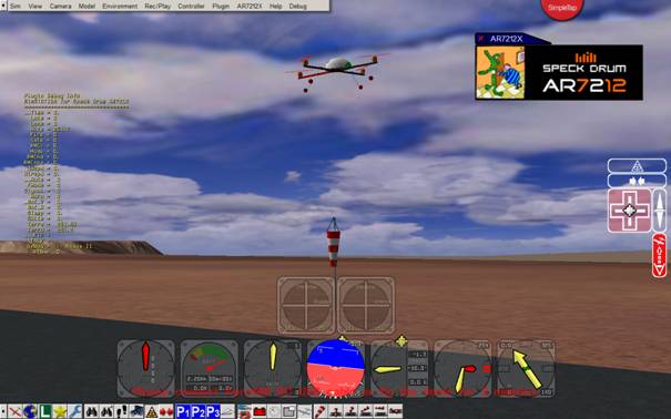
To enable the visualization of kiXAHRS_ONE
within AerosimRC, select the kixline format, 115200 bps, 15000 mics, and store
these settings in EEPROM. The plugin comes with the plugin_kixAHRS_AerosimRC.ZIP
folder. Find instructions how to install in the kixPLUGIN_README2.txt
Please note that updates of kixAHRS_ONE
will be in the AR7212 folder of the Forum at MCS electronics.
Have fun
Natalius