The BASCOM LT TEST PCB is a development system intended to be used along
with BASCOM LT, but can be used with other software as wellBASCOM TEST PCB
The BASCOM LT TEST PCB is a development system intended to be used along
with BASCOM LT, but can be used with other software as well. It is designed by the
Slovenian Electronics magazine Elektronike from AX Elektronika d.o.o.
The development system supports the following chips :
- ATMEL 20-pin CPU's (AT89C1051, AT89C2051)
|
- ATMEL AVR CPUs (AT90S1200, AT90S2312)
|
- ATMEL 40-pin CPU's (AT89C51, AT89C52, AT89C55, AT89C8252, AT89S53, AT90S4414,
AT90S8515).
|
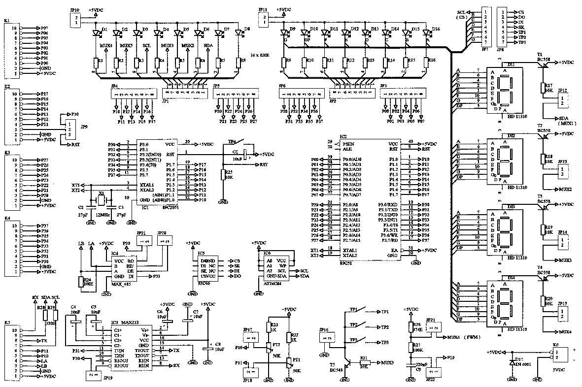
The TEST PCB is designed with special care to support as much CPU
functions as possible. LCD/LED display, switches, I/O ports and RS232.
All I/O ports are accessible via connectors K1-K4, which are intended to
connect the TEST PCB to the target system. An exception is K2.
With the use of the jumper, the pin No.:3 can be switched between P10 and RST.
This enables the CPU to be programmed in circuit via SPI bus (this applies to those CPUs,
that have SPI bus).
The K5 connector is the RS232 communications connector.
The RX/TX for the RS232, LA/LB for the RS485 and SDA/SCL for the I2C are connected to K5.
The K5 has also access to P10 and P11, which are inputs to the analog comparator.
The trimmer pots PT1 and PT2 are connected to P11 and P10 respectively via jumpers JP18
& JP17.
The R26, R27 and C9 are intended for the A/D conversion and can be enabled/disabled via
jumpers JP22 and JP23.
Jumpers on the TEST PCB are intended to configure the system upon user's requirements.
The I/O ports status can be monitored won the LED diodes.
D1-D8 show the P1/P2 status.
The whole line of LED's can be switched on/off via jumper JP10.
The same applies to LED's D9-D16, that show the status of the ports P0/P3.
Four 7-segment LED displays are also connected to the jumpers and can be switched
on/off via jumpers JP12-JP15.
The switches TP1-TP3 are connected in multiplexed mode (MUX5).
Beginners however might have problems with this. Therefore the multiplex mode can be
turned off via jumper JP16.
The switch TP4 is the CPU RESET switch.
The TEST PCB supports two commonly used EEPROM's: 93C64 and 24C04.
Due to hardware both of them cannot be used simultaneously.
The TEST PCB has the clock requirements solved with the 12 MHz
X-TAL, that is used for both - 20-pin and 40-pin CPUs.
Schematic
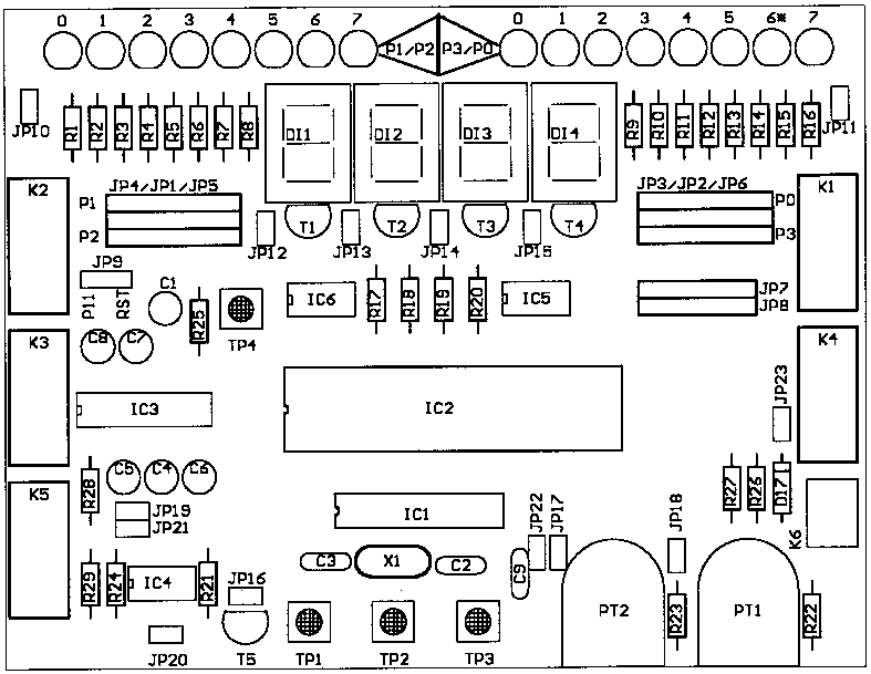
Silk screen
-
|