The Stack is a part of SRAM (Static RAM).
). In SRAM the compiler stores user dimensioned variables, as well as internal
variables, but SRAM holds also Hardware Stack, Software Stack and Frame. The
Variables always start at the lowest SRAM Address. After Reset all SRAM Bytes
are 0 (and strings are "") so the SRAM memory is cleared after reset.
With the $noramclear option you can turn this behavior off which means the SRAM
is not cleared after reset.
The available SRAM depends on the Chip.
With ATTINY13 for example you have 64Byte
of SRAM and you will find this information beside the user manual in the *.DAT
file. You can also double click the chip in Chip Pinout to view the chip
parameters.
The following you find in the attiny13.dat
file: SRAM = 64 ;
SRAM size
Global Variables start with the lowest SRAM
Address and the Hardware Stack start with the highest SRAM Address.
$regfile = "attiny13.dat"
$crystal = 4000000
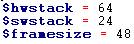
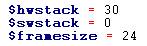
$hwstack = 30
$swstack = 0
$framesize = 24
Dim B As Byte
B = 5
Pcmsk = &B00000001 'PIN Change Int
ON PCINT0 pin_change_isr
Set Gimsk.5
Enable Interrupts
Do
!NOP
Loop
End 'end program
pin_change_isr:
B = 7
Return
|
|

Picture1 : Memory of ATTINY13
With an ATTINY13 the SRAM is just 64Byte
and it is easy to see which SRAM Bytes will be overwritten with Bascom AVR
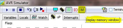
Simulator Memory Window.
Click on M to display the memory
window.
Picture 2: SRAM of ATTINY13 when executing
the above ATTINY13 example in Bascom Simulator
You can see the Hardware Stack (32 Byte) ,
Frame (24 Byte) and the Variable B.
For this example you do not really need a
Frame so it could be also $framesize = 0 for this example.
With ATXMEGA128A1 there is 8K Byte of SRAM
available (SRAM = 8192 ; SRAM size
)
The Values of Stack should be ALWAYS
defined at the beginning of any BASCOM-AVR Program in the main project file.
The best place is right after the $REGFILE statement.
Example:
You can also use the Add to Code function
in BASCOM Menu: COMPILER >>> OPTIONS >>> CHIP
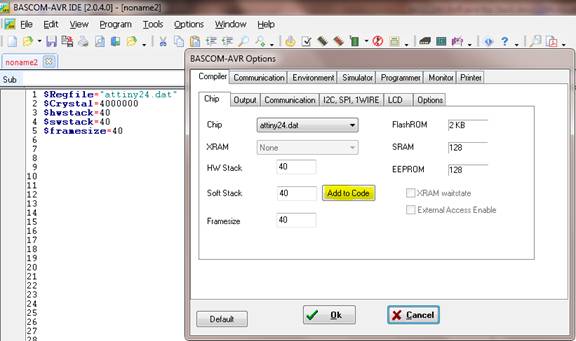
Picture 3 : BASCOM-AVR CHIP Options
Hardware Stack ($hwstack):
The Hardware stack is room space in SRAM
that is needed by your program. Each time you call a SUB or FUNCTION, or use
GOSUB, the processor need to know at which address to return after returning
from the call. Also for RETURN Address after Interrupt this is needed by the
program. For this purpose, the processor saves this address on the hardware
stack.
When you use GOSUB label, the
microprocessor pushes the return address on the hardware stack and will use 2 Bytes
for that. When you use RETURN, the Hardware stack is popped back and the
program can continue at the proper address. When you nest GOSUB, CALL or
functions, you will use more stack space. Most statements use HW stack because
a machine language routine is called.
The Hardware Stack is growing top down (see
picture 8). The Hardware Stack start at the highest available SRAM Address and
therefore is located before Software Stack and/or Frame.
For further information search in the user
manual of ATTINY, ATMEGA or ATXMEGA for Stack Pointer.
Example for using an Interrupt and examine Hardware
Stack:
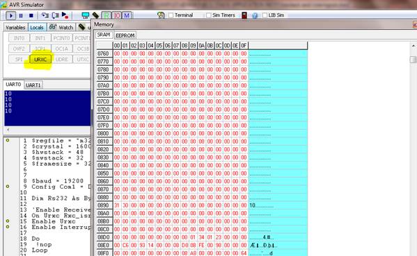
With the following example we just define
and enable the Receive Interrupt of the UART and examine when clicking on
Interrupt button within the Bascom-AVR Simulator Interrupts Tab how many
Hardware Stack is needed.
$regfile = "m328pdef.dat"
$crystal = 16000000
$hwstack = 48
$swstack = 32
$framesize = 32
$baud = 19200
Config Com1 = Dummy , Synchrone = 0 , Parity = None , Stopbits = 1 , Databits = 8 , Clockpol = 0
Dim Rs232 As Byte
'Enable
Receive Interrupt for COM1
On Urxc Rxc_isr
Enable Urxc
Enable Interrupts
Do
!nop
Loop
End
Rxc_isr:
Rs232 = Inkey()
Print Rs232
Return
With this example we see (by counting the
changed SRAM Bytes in Bascom Simulator Memory Window) that Software Stack is
NOT needed but at least 39 Byte of Hardware Stack and the Frame with the
24 Byte conversion buffer because of PRINT.
Most of the 39
Bytes are the saved Registers when jumping in Interrupt Service Routine. These
are SREG , R31 to R16 and R11 to R0 with exception of R6,R8 and R9.
The following
should be considered in any case (not only when using NOSAVE):
Take care when
using floating point math in the ISR because the Register R12 to R15 are not
saved in the regular process of processor register backup. Using floating point
math in ISR is not recommended anyway.
When you try the
same example with NOSAVE ( ) you will see the example will need less Hardware Stack but you
are responsible then to save all of the Registers with PUSH and POP in the
Interrupt Service Routine that are needed or changed during the Interrupt
Service Routine.
) you will see the example will need less Hardware Stack but you
are responsible then to save all of the Registers with PUSH and POP in the
Interrupt Service Routine that are needed or changed during the Interrupt
Service Routine.
The easier, and
above all safer way is not using NOSAVE which is also the default way.
Picture 4 : The Hardware Stack will be
filled by clicking the Bascom-AVR Simulator Interrupt:
Picture 5 : By clicking on the Interrupts
Button will fire an interrupt in Simulator
Take also care when using Config Serialin in combination with UART when you
want to use the BYTEMATCH option. In this case NOSAVE is DEFAULT so you need to
PUSH and POP the Registers you use during the Interrupt Service Routine. The
easy way out is using PUSHALL and POPALL but this is also the most
time-consuming way in regards of cycles needed to go though the ISR.
Serial2charmatch:
Pushall
'Your code
here !
Popall
Return
How to determine which Register are changed during an
Interrupt Service Routine when using NOSAVE option ?
When using NOSAVE you are responsible to
PUSH and POPP the register
For this we use the same code as in the
example before but use the NOSAVE option:
$regfile = "m328pdef.dat"
$crystal = 16000000
$hwstack = 48
$swstack = 32
$framesize = 32
$baud = 19200
Config Com1 = Dummy , Synchrone = 0 , Parity = None , Stopbits = 1 , Databits = 8 , Clockpol = 0
Dim Rs232 As Byte
'Enable Receive
Interrupt for COM1
On Urxc Rxc_isr NOSAVE
Enable Urxc
Enable Interrupts
Do
!nop
Loop
End
Rxc_isr:
Rs232 = Inkey()
Print Rs232
Return
Compile it and open Bascom Simulator. Under
µP you find a Button with the Snapshot function.
With Snapshot you see which register values
are changed and we use this to see which register values are changed during the
Interrupt Service Routine.
Run the Simulator  then goto µP Tab.
Click on Snapshot then switch to the
Interrupts Tab and click on the URCX Button which fires an Interrupt.
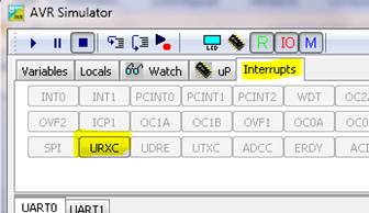
Picture 6: Interrupts in Bascom Simulator
Then go back to µP Tab and click on STOP
Snapshot.
Now you see the changed Registers and can
add the PUSH and POP to the Interrupt Service Routine.
Picture 7: How to determine which Register
are changed during an Interrupt Service Routine
When registers are changed which are not in
the first 32 Register so search for Register Summary in the user manual of
for example ATMEGA devices.
$5F for example is the SREG Register for
an ATMEGA32.
One solution for the ISR for this example
is:
Rxc_isr:
push r0 '
save used register
push r10
push r24
!in r24,sreg ' save sreg
push r24
push r25
push r26
push r30
Rs232 = Inkey()
Print Rs232
pop
r30
pop r26
pop r25
pop r24
!out sreg,r24 ' restore sreg
pop r24 ' and the used register
pop r10
pop r0
Return
Software Stack ($swstack):
Software Stack stores the parameter
addresses passed to a subroutine and LOCAL variable addresses.
So the Software stack stores the addresses
of variables where each passed variable and local variable use 2 bytes per
respective addresses.
When using SUB or FUNCTION there are 3 ways
for parameters:
· Using BYREF pass a variable by reference with
its ADDRESS (so it is pointing to an existing variable which is already in
SRAM)
· Using BYVAL the value is stored in FRAME (during
the SUB is processed) so it is pointing to the address in FRAME.
· Using BYLABEL pass the address of a label
When nothing is specified the parameter
will be passed BYREF.
If you have used 10 locals in a SUB and
there are 3 parameters passed to it, you need:
(10 * 2 Byte) + (3 * 2 Byte) = 26 Byte
Software Stack.
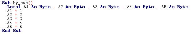
The following SUB need 10 Byte of Software
Stack:
5* 2 Byte = 10 Byte
So the software stack size can be
calculated by taking the maximum number of parameter passed to a SUB routine,
adding the number of LOCAL variables and multiplying the result by 2. To be
safe, add 4 more bytes for internally used LOCAL variables.
If you have several SUB or FUNCTIONS search
for the SUB or FUNCTION with the most parameters and LOCAL variables
and use that calculated maximum numbers for defining the Software Stack
($swstack).
The Software Stack is growing top down (see
picture 8) and start direct after the Hardware Stack. The Software Stack grows
against the FRAME.
Picture 8: Memory of ATXMEGA128A1
Frame ($framesize)
Functions like PRINT, LCD, INPUT and the FP
num <> FORMAT(), String conversion routines require a buffer in SRAM.
Because of that the compiler always is using 24 bytes of frame space.
This 24 Byte start at the beginning of the Frame which act as the conversion
buffer within the frame. (See also picture 8).
Because the FRAME is growing bottom up and
this 24 Byte start at the beginning of the FRAME this 24 Byte conversion buffer
start at the lowest FRAME Address (See picture 8). Here you also see that a too
small $framesize causes an overwriting of Software Stack and/or Hardware Stack
which lead to malfunction.
A LOCAL variable is a temporary variable that is stored in
frame.
There can be only LOCAL variables of the type BYTE,
INTEGER, WORD, LONG, SINGLE, DOUBLE or STRING.
A LOCAL Integer will use 2 Bytes of Frame ,
A LOCAL Long will use 4 Bytes.
A LOCAL string * 20 will use 20 + 1 = 21
Byte (this additional 1 Byte is because every String is terminated with a
0-Byte)
When the SUB or FUNCTION is terminated,
the memory will be released back to the frame but the FRAME will not be cleared
! Therefore a LOCAL variable is not initialized. So you can not assume the
variable is 0. If you like it to be 0, you need to assign it !
BIT variables are not possible as LOCAL
because they are always GLOBAL to the system.
Arrays can NOT be used as LOCAL (but
arrays can be passed by REFERENCE as parameter to SUB and FUNCTIONS which just
need 2 Bytes Software Stack of the Address of Array start)
Example FRAME calculation:
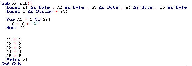
Now we calculate the FRAME:
The Print A1 will be placed in the first
frame-Byte of the 24 Byte conversion buffer.
5 LOCAL Byte (A1
A5) = 5 Byte of FRAME
LOCAL String: 254 Byte + 1 Byte = 255 Byte
Frame needed = 24Byte Frame conversion
Buffer + 5 Byte + 255 Byte = 284 Byte
This can be easy double checked with
BASCOM-AVR Simulator (see picture 9 on next page).
In picture 9 you see the start of FRAME
which start with the 24Byte conversion buffer. The 31 in the first Frame Byte
is from Print A1. After the 24 Byte conversion buffer follow the 5 Local Byte
variables (A1
. A5) and then the 255 Byte for the LOCAL String.
Picture 9 Memory window of BASCOM-AVR
Simulator (Frame calculation example)
As with Software Stack you need to
calculate the Framesize needed by the SUB or FUNCTION with the most LOCAL
Variables and parameter passed by REFERENCE etc..
Take care when calling a SUB within a SUB.
In this case you need to add the FRAME needed by both SUB !
When both SUB need 284 Byte you need to
use:
24 Byte conversion Buffer + 2* 5 Byte
(A1
A5) + 2*255 Byte (String) = 544 Byte
(the conversion buffer is needed only once
!)
Following you find the full example for
calculation of FRAME:
$regfile = "xm128a1def.dat"
$crystal = 32000000 '32MHz
$hwstack = 64
$swstack = 128
$framesize = 288
$lib "xmega.lib"
$external _xmegafix_clear
$external _xmegafix_rol_r1014
Config Osc = Enabled , 32mhzosc = Enabled '32MHz
'configure the
systemclock
Config Sysclock = 32mhz , Prescalea = 1 , Prescalebc = 1_1 '32MHz
'Config
Interrupts
Config Priority = Static , Vector = Application , Lo = Enabled 'Enable Lo Level Interrupts
Config Com1 = 57600 , Mode = Asynchroneous , Parity = None , Stopbits = 1 , Databits = 8
Declare Sub My_sub()
Call My_sub()
End 'end program
Sub My_sub()
Local A1 As Byte , A2 As Byte , A3 As Byte , A4 As Byte , A5 As Byte
Local S As String * 254
For A1 = 1 To 254
S = S + "1"
Next A1
A1 = 1
A2 = 2
A3 = 3
A4 = 4
A5 = 5
Print A1
End Sub
Testprogram for following examples:
For further investigation of Stacks and
Frame we use a SUB with 5 LOCAL Byte Variables and a PRINT function within the
SUB. We start with hwstack, swstack and framesize defined and in second step we
set swstack to 0. In addition we will lower the framesize to a not recommended
value to force overwriting of other stack bytes.
$regfile = "xm128a1def.dat"
$crystal = 32000000 '32MHz
$hwstack = 64
$swstack = 128
$framesize = 256
$lib "xmega.lib"
$external _xmegafix_clear
$external _xmegafix_rol_r1014
Config Osc = Enabled , 32mhzosc = Enabled '32MHz
'configure the
systemclock
Config Sysclock = 32mhz , Prescalea = 1 , Prescalebc = 1_1 '32MHz
'Config Interrupts
Config Priority = Static , Vector = Application , Lo = Enabled 'Enable Lo Level Interrupts
Config Com1 = 57600 , Mode = Asynchroneous , Parity = None , Stopbits = 1 , Databits = 8
Declare Sub My_sub()
Call My_sub()
End 'end program
Sub My_sub()
Local A1 As Byte , A2 As Byte , A3 As Byte , A4 As Byte , A5 As Byte
A1 = 1
A2 = 2
A3 = 3
A4 = 4
A5 = 5
Print A1
End Sub
The first example use $hwstack = 64, $swstack = 128,
$framesize = 256
Here we see the 64 Byte Hardware Stack
followed by 128 Byte Software Stack and then 256 Byte Frame. As always the
Frame is the 24 Byte conversion buffer + rest of frame.
Picture 10 : SRAM for Example with $hwstack
= 64, $swstack = 128, $framesize = 256
The Simulator Memory Window show give us
the details:
Picture 11: Simulator Memory Window for
Example with $hwstack = 64, $swstack = 128, $framesize = 256
The second example use $hwstack = 64, $swstack = 0, $framesize = 256
Without defining a software Stack or with
$swstack = 0 the Frame follows direct after the Hardware Stack. The Frame is as
always 24 Byte conversion buffer + Rest of Frame.
Rest of Frame is in this case: 256 Byte
24 Byte = 232 Byte
Picture 12: SRAM for example with $hwstack
= 64, $swstack = 0, $framesize = 256
In the BASCOM Simulator Window you now see
the addresses of the LOCAL variables are now stored in FRAME (which are usually
in the Software Stack). This is not a problem as long as the Frame is big
enough not to overwrite these addresses of the LOCAL variables.
(Remember: Address of LOCAL
variables are stored in Software Stack (when Software Stack is defined) . The
LOCAL Variables itself are stored in FRAME)
And here you see also with the 24 Byte
conversion buffer the absolute minimum you need to define for software Stack
and Framesize together is 24 Byte !
But this is not the recommendation. The
recommendation is always define values for all Stack and Frame !
Picture 13: Simulator Memory Window for Example
with $hwstack = 64, $swstack = 0, $framesize =
256
For an ATXMEGA or ATMEGA you have usually
enough SRAM so you can start with higher values of Stack and Frame.
With an ATTINY13 and 64Byte SRAM it is a
challenge but also start with all stack defined and lower the Stack Values when
your application program grows.
· Dont use SUB or FUNCTIONS
· If you use Functions like PRINT, LCD, INPUT and
the FP num <> FORMAT(), String conversion you need to define the 24
Byte conversion buffer (at least 24Byte for Software Stack + FRAME together).
In this case just 9 Bytes
are left for global variables !
The third example show what can happen when you define NO
Stacks or Frame (which is still often seen in Forums) or when you define not
enough Stack or Frame. In this example we use:
$hwstack = 64, $swstack = 0, $framesize = 8
As we know now Software Stack and FRAME
together must be as absolute minimum 24 Byte (for the conversion buffer) so we
force the overwriting of Hardware Stack which causes malfunction.
(Reminder: Dont start with the lowest
values for Stack and Frame)
Picture 14 : SRAM for example with$hwstack
= 64, $swstack = 0, $framesize = 8
You can now imagine what could happen:
· Because of overwritten return address in
Hardware Stack the micro is jumping to somewhere else and malfunction if
forced.
· Functions like PRINT overwrite addresses of
LOCAL Variables and here also will the micro jump to somewhere else and
malfunction is forced.
Picture 15: Simulator Memory Windows for
example with $hwstack = 64, $swstack = 0,
$framesize = 8
Now an example for passing an Array to a SUB:
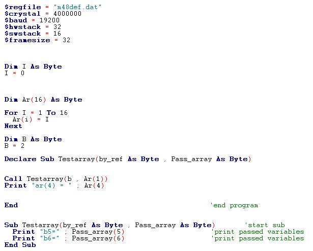
With this example we see the complete SRAM.
The SRAM start with the dimed variables. In
this case it start with the variable I
followed by the Array Ar of 16 Byte and in
the end the variable B.
Because it is easier with the memory window
of Bascom Simulator I choose multiple of 16 for Stack and Framesize.
We have here 2 Addresses stored in Software
Stack. One address for the Array and one address for the variable B.
So passing an Array to a SUB just need 2
Bytes for the address in Stack which is the same size as for one Byte variable
(her variable B).
Picture 16: Simulator Memory Window for
example passing an Array to a SUB
With this example you also see that
especially with ATTINY and smaller ATMEGA it is not that complicated to see if
other SRAM bytes will be overwritten by something and causes malfunction.
You have with the Simulator window the big
picture of SRAM and STACK together.
As already written it is easier to use
multiple of 16 for Hardware Stack, Software Stack and FRAME as a starting point
because one line in Simulator Memory window is 16 Bytes.
How to see which Variables are stored on which SRAM Byte
?
This is only possible for the variables
itself and not for the address of an variable.
You can find out the stored variable with
the Bascom-AVR Simulator Memory Window by clicking on that byte.
Click on SRAM Bytes show the OCCUPIED BY
in the footer of that window.
Only the first Byte of an Array will
show the Name of the Array !
Picture 17: How to see which Variables are
stored on which SRAM Byte
You can also find this information in the
Compiler output report:
In this case under VARIABLES
Picture 18: How to see which Variables are
stored on which SRAM Address
Internal Variables in the Bascom-AVR Simulator Memory
Window
The following small example is good for
examining the Bascom-AVR internal variables like _sec, _min or _hour in
Bascom-AVR Simulator Memory Window.
Config Clock = User for example create the internal variables for seconds (_sec),
minutes (_min) ,hour (_hour) etc
. You can see this variables by clicking on
the SRAM Byte and watch the footer of that Bascom-AVR Simulator Memory Window
footer.
$regfile = "m88def.dat"
$hwstack = 48
$swstack = 80
$framesize = 80
Config Clock = User
End 'end program
Picture 19: Internal Variables in the
Bascom-AVR Simulator Memory Window
List of References:
BASCOM-AVR Help
File
MCS-Electronics
MAK3
MWS
Bascom Forums:
http://www.mcselec.com/index2.php?option=com_forum&Itemid=59
http://bascomforum.de/
Used Bascom-AVR
Version = 2.0.4.0


