|
|
| |
|
|
| |
|
AN #181 - demonstrating the DCF77 and I2C |

|
A DCF77 clock receives time information from a broadcast station located near Frankfurt, in Germany.
by electromicro
Introduction :
A DCF77 clock receives time information from a broadcast station located near Frankfurt, in Germany. More informations can be found here :
http://en.wikipedia.org/wiki/DCF77
And also here, it is continuously displayed in live the signal broad casted by DCF77
http://www.dcf77logs.de/WebConsole.aspx
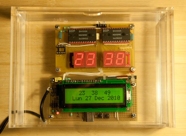
On the clock described here, hours, minutes, seconds, date, day, month and year are displayed on an LCD.
There are also a four 7 segments display where, for a better time readability, hours and minutes are also displayed.
DCF77 reception :
At power on, the clock will synchronize itself on DCF77. There is no other way to put the clock on time: its a no manual adjustment clock (the two switches visible on the picture are not used in this application).
The synchronization with DCF77 can take some minutes (at least three), depending of the level and noise on the signal received. Perturbations due by the distance from the broadcast station and the local reception conditions (i.e. reinforced concrete act like a shielding at 77.5 Khz.).
For better reception, ferrite antenna has to be perpendicular to Frankfurt (its not a joke !).
The receiver itself is a dcf77 module available from Selectronic :
http://www.selectronic.fr/article.asp?article_ref_entier=11.1143-9999
The connexions are : 1= Output, 2 = +5volts, 3 = standby (receive if 0) 4 = 0 Volt.
Signal on pin 1 is positive and does not work if connected to a pull-up resistor...
The signal of the pin 1 has to be connected to pin 13 (PD7) of the micro controller though a 4,7 K resistor (this in order to avoid to kill the receiver output if, by mistake, PD7 is configured as an output and set to 1).
A similar receiver is also available from Conrad :
http://www.conrad.de/ce/de/product/641138/?insert=62&insertNoDeeplink&productname=DCF-EMPFAENGERPLATINE
or :
http://www.conrad.fr/platine_de_reception_dcf_p_48674_49802_836661_213107_FAS
In accordance with Conrad documentation and for their DCF77 receiver :
The connexions are : 1 = 0 Volt, 2 = +1.2 to +15 volts, 3 = DCF Output, 4 = Inverted DCF Output.
Must be used Pin3, DCF output not inverted.
And also as outputs are open collector (with a max sink current of 1 mA), it is mandatory to add a 10 K pull-up resistor between output used and + 5 volts, or modify the program to put in use the micro controller pull-up resistor on PortD.7.
I have not tried the Conrad receiver but it should works.
It is better to avoid close distance of the antenna with any metallic part, acting like rf shied.
The antenna is fitted without metallic parts, using adhesive foam tape and ty-wrap (see pictures).
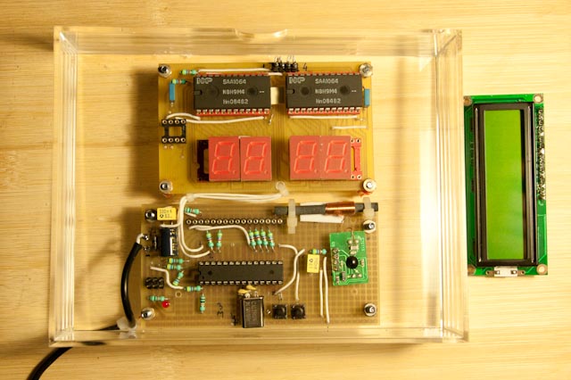
Microcontroller and lcd board :
The microcontroller used is an ATMega 8-16PU, with a 16 Mhz Xtal oscillator.
On the schematic are showed inter-connexions between micro controller, ISP connector and a standard LCD display with 2 lines of 16 characters.
As this schematic is also used on some others applications, there is some resistors added on it.
This in order to share the programmer pins with the lcd, to have a maximum of microcontroller pins available free.
There are some more resistors : they are used to avoid microcontroller output shorts in others uses of this board, and also as connections straps on the pcb.
Except that there is nothing of special to said on this classic schematic (dont forget the decoupling capacitors !).
It is normally possible to use any other AVR microcontroller and board already available (with the same microcontroller or equivalent),
To do that, it will be necessary to change the relevant initialization parameters on the Bascom program. No tests have been done with any other board.
Note : on the picture are visible two switches : they are not used in this application.
Seven segments board :
Then there is the schematic of the 7 segments display board.
There are only four connections with the micro-controller board :
+ 5 volts, 0 volt, SCA (pin 27 microcontroller), SCL (pin 28 microcontroller)
For better readability four common anode seven segments are used, driven by two SAA1064.
Seven segments reference are LTS-546AHR, (any 7 segments with common anode can be used) :
http://www.datasheetarchive.com/pdf-datasheets/Datasheets-8/DSA-151063.html
Use of two SAA1064 allow 7 segments to be driven in static mode instead of dynamic mode.
Difference between both modes are :
In static mode, display is continuous on two 7 segments.
In dynamic mode, display is altered on four 7 segments (at around 100 Hz).
Dynamic mode produce, with its 10 mS refresh period some RF noise disturbing DCF77 signal reception.
In static mode, there is only one refresh per minute.
This is the reason of the design choice.
A tip : Even the SAA1064 are set to limit the current on each segment to the minimum value : 3 mA, it can appear than brightness can be too high.
This is certainly due to the fact than SAA1064 are old chips and 7 segments have been improved, in terms of brightness.
In this case, the most convenient way is to add in front of the 7 segments a piece of Clear, colored pvc ref 604 Super Sheets made by Raboesch in The Netherland :
http://www.raboesch.com/english/cat1_sheets.htm
Or any other optical filter glued or put in front to dim the 7 segments, because an electronic way is not so easy in this case...
Same optical filter can be also used for the lcd.
On the 7 segments schematic appear a PCF8583 and its Xtal: They are not used on this realization, and must not to be put in place.
A comment :It is not absolutely necessary to make a pcb for the 7 segments board.
A prototype board can be used but there is many wires to solder. In this case, it is convenient to use teflon insulated wires, a no burnable insulation with soldering iron made connections more easy.
Power supply :
For safety, power supply is totally external to the clock.
It has been used an AC/DC switching power supply 5 volts 500 mA.
It is enclosed in a box, directly plugged on the 230 volts.
This model has been used, but any other can fit:
http://www.selectronic.fr/article.asp?article_ref_entier=11.0451-9999
The box
The choice has been made to use an clear acrylic box, in order to see the electronic though it.
This model has been used (external size : w17.5 x d13 x h4.8cm.) :
http://www.muji.eu/pages/online.asp?V=1&Sec=17&Sub=69&PID=2423
In fact, its a drawer sliding inside a box.
The two PCB are fitted with screws thought the drawers back, then the drawer is slided into the box and fitted with adhesive tape.
If required, it is very easy to insert between the drawer and the box a piece of PVC, cut at the drawer size. The electronic is no more visible, but it is possible to see the light of lcd and 7 segments.
With is a locator to find a shop :
http://www.muji.com/storelocator/
But obviously, any box can be used, its a personal choice.
Why not to try a marble or a wooden box ?
Bascom Software :
When all the hardware is build, Bascom .hex program has to be loaded in the micro controller, using ISP connector and a relevant AVR programmer.
If all is OK Miracle: after a few minutes (minimum three) for the DCF77 synchronization, time and date will be displayed !!!
For any purpose use: on the PortD.6, pin 13 of the micro controller, there is a positive 40 milliseconds signal, starting at each 1 second interrupt.
Its a convenient one second time base, but keep in mind:
Due to the level variations of the DCF77 received signal, the automatic gain control of the receiver adjust continuously the triggering level for the signal detection and a small jitter will exist on this signal (around 1 or 2 milliseconds ?). But the period number is exact !
The program is very short : two pages.
Thanks to the config dcf77 Bascom instruction : with a PIC and another basic compiler, it take to me 13 pages of program to have exactly the same realization done !
Synchronization with dcf77 is continuous (as long as reception is correct). In case of signal disturbance, the clock is generated by the software behind config dcf77.
It is very easy to customize this program to specific needs, ie :
1. The Main program itself is only 3 Bascom instructions :
Do
NOP
Loop
All is performed in the interrupts, their duration is around 40 millisecond, each second, (measurement possible on PortD.6 as explain before).
It remain a lot of time (1 second 40 ms) to customize the program to specific needs !
2. At the end of the program, there is two instructions where can be replaced French abbreviations for days and months, to have a display with the preferred language.
3. If the 7 segments display is not needed, do not connect it and delete relevant instructions in the program.
4. To fulfill with special needs, it is possible to modify the parameters of the Bascom instruction config dcf77. Please refer to the Bascom language reference of the Bascom Help.
Troubleshooting :
- Before first power on, check if there are no shorts circuits !
- Power led and lcd light should goes on immediately at power on.
- If nothing is displayed on lcd, check for short or bad wiring somewhere.
- At power on, a splash screen with program file name and its revision date is displayed during three second. If not, programm is perhaps not running: verify micro controller fuses and Xtal.
- If 7 segments board is not connected, program will wait for it. In this case, delete relevant lines on the program
- If time is displayed on lcd line 1 with incrementation every second and Synchro is displayed on line 2 : No or bad DCF77 signal reception In this case : Try another orientation of the antenna, another place in the room, (avoid proximity of dimmer, fluo lights, 220 volts led bulbs also!). Verify with another DCF77 clock if there is a signal reception at this place. Verify with an oscilloscope the DCF77 receiver output to see if there is no signal or a signal with erratics pulses due to rf noise.
Enjoy !
Sample program :
'--------------------------------------------------
' DCF 77 clock with lcd display and 7 segments
'--------------------------------------------------
' Date and Filename : to see around line 17
'--------------------------------------------------
$regfile = "M8def.dat"
$crystal = 16000000
Config Lcd = 16 * 2
Config Lcdpin = Pin , Db4 = Portb.5 , Db5 = Portb.4 , Db6 = Portb.3 , Db7 = Portb.2 , E = Portc.2 , Rs = Portc.3
Initlcd
Cls
Cursor Off
'-----Clock program splash screen-----------------
Lcd "DCF77 01/01/2011"
Lowerline
Lcd "Tst_dcf77_7"
Wait 3
Cls
'-------------------------------------------------
Config Pind.6 = Output 'for test purpose :
Config Dcf77 = Pind.7 , Inverted = 0 , Timer = 1 , Debug = 0 , Check = 1 , Gosub = Sectic
'to have an input port without pull up resistor (for DCF77 module out):
Config Pind.7 = Input
Portd = Portd And &B01111111
Config Date = Dmy , Separator = .
Declare Function Dcf_timezone() As Byte
Dim I As Integer
Dim Sec_old As Byte , Dcfsec_old As Byte
Dim Dof As Byte
Dim Strdate As String * 8
Dim Bday As Byte , Bmonth As Byte , Byear As Byte
Dim Bweekday As Byte , Strweekday As String * 3
Dim Bmonthname As Byte , Smonthname As String * 3
Dim Strtime As String * 8
Dim Bsec As Byte , Bmin As Byte , Bhour As Byte
Dim Indcf As Byte
'i2c initialization
Config Scl = Portc.5 'scl = PC5 = pin 28
Config Sda = Portc.4 'sda = PC4 = pin 27
Dim Min7seg As Byte
Dim Min7segleft As Byte
Dim Min7segright As Byte
Dim Hour7seg As Byte
Dim Hour7segleft As Byte
Dim Hour7segright As Byte
Dim Mask1 As Byte
Dim Mask2 As Byte
I2cinit
Enable Interrupts
'--- "Main" program !!! -----------------------------------
Do
nop
Loop
'------------------------------------------------------
'Called every second by the library:
Sectic:
'for test purpose: interrupt durat 40 ms each second, more each minute.
Set Portd.6
'Converting Time-string to defined Clock - Bytes (Second / Minute / Hour)
Strtime = Time$
Bsec = Time(strtime)
'display time on lcd line 1
Home
Locate 1 , 4
If Bhour < 10 Then Lcd " " ; Bhour Else Lcd "" ; Bhour
Locate 1 , 8
If Bmin < 10 Then Lcd " " ; Bmin Else Lcd "" ; Bmin
Locate 1 , 12
If Bsec < 10 Then Lcd " " ; Bsec Else Lcd "" ; Bsec
'Converting day number in day abbrevation
Bweekday = Dayofweek()
Strweekday = Lookupstr(bweekday , Weekdays)
'Converting Date - String to defined Clock - Bytes (Day / Month / Year)
Strdate = Date$
Bday = Date(strdate)
'Converting month number in month abbrevation
Bmonthname = Bmonth
Smonthname = Lookupstr(bmonthname , Monthdays)
'Lowerline 'Display date on lcd line 2
If Dcf_status.7 = 0 Then 'test if dcf77 in sync
Locate 2 , 2
Lcd "Synchro..."
Else
Locate 2 , 2
Lcd Strweekday
Locate 2 , 5
If Bday < 10 Then Lcd " " ; Bday Else Lcd " " ; Bday
Locate 2 , 8
Lcd " " ; Smonthname
Locate 2 , 13
Lcd "20"
Locate 2 , 15
Lcd Byear
'Lcd " " ; Strweekday ; " " ; Bday ; " " ; Smonthname ; " 20" ; Byear
End If
Reset Portd.6 'test point purpose
'Minutes on 7 segments time display
If Min7seg = Bmin Then
Goto Sortie
Else
Min7seg = Bmin
End If
Min7segleft = Min7seg / 10
Min7segright = Min7seg Mod 10
Mask2 = Lookup(min7segleft , Display7seg)
Mask1 = Lookup(min7segright , Display7seg)
I2cstart
I2cwbyte &H70 'slave address
I2cwbyte 0 'instruction byte
I2cwbyte &H16 'control byte
I2cwbyte Mask1 'Mask1
I2cwbyte Mask2 'Mask2
I2cstop
'Hours on 7 segments time display
If Hour7seg = Bhour Then
Goto Sortie
Else
Hour7seg = Bhour
End If
Hour7segleft = Hour7seg / 10
Hour7segright = Hour7seg Mod 10
Mask2 = Lookup(hour7segleft , Display7seg)
Mask1 = Lookup(hour7segright , Display7seg)
I2cstart
I2cwbyte &H76 'slave address
I2cwbyte 0 'instruction byte
I2cwbyte &H16 'control byte
I2cwbyte Mask1 'Mask1
I2cwbyte Mask2 'Mask2
I2cstop
Sortie:
Return
End
'----------------------------------------------------------
Weekdays:
Data "Lun" , "Mar" , "Mer" , "Jeu" , "Ven" , "Sam" , "Dim"
Monthdays:
Data " " , "Jan" , "Fev" , "Mar" , "Avr" , "Mai" , "Jun" , "Juil" , "Aou" , "Sep" , "Oct" , "Nov" , "Dec"
Display7seg:
Data &H3F , &H06 , &H5B , &H4F , &H66 , &H6D , &H7D , &H07 , &H7F , &H6F |
|
|
| |
|
|
|