by Natalius Kiedro (software) and Ralf Kull (hardware)
Summary
This AN gives an overview about the Speck Drum AR7212 (seven to twelve) receiver and introduces its hardware. It is the first of a miniseries of 3 AN's. The second will explain the AR7212 programmer, a Windows PC program from which the receiver gets its servo and mixer data when connected to the PC/laptop via USB cable. A third AN will introduce extensions: telemetry, flight stabilization and a GPS-autopilot aiming to improve the safety of RC flight.
Background
The market for RC technology is currently undergoing a major transition. For decades aero-modellers preferred exclusive bands (35 MHz in Europe, and e.g. 72 MHz in the US) and a standardized transmission protocol based on pulse position modulation (PPM). There was no real protection against double occupation of a given RC frequency channel, every RC pilot in a club had to ensure that his channel is not in use before switching on his radio. The standardization of PPM however prevented brand binding, viz. receivers of brand A could be used with radios from company B in many cases. With the introduction of the 2.4 GHz ISM-band and its utilization by RC-modellers things have changed completely. Flight safety has definitely improved by now, but brand binding has increased as well. What is also little pleasant for the budget of the modeller is a phenomenon that we would like to coin the RC price law
The RC price law
When averaging the price P for a radio with N servo channels over many brands, it looks that
P(N+2) = 2 P(N)
roughly describes how radio and receiver producers are shaping their prices today. In words: Pay the double price for a radio which has two channels more. Let us assume that a radio-receiver combo for 7 channels comes for 300 , then the combo for 9 channels is expected to have a price of about 600 , and a 11-channel combo will be about 1200 . As 11-channel radios are somehow odd the manufacturer may decide to offer the 12-channel variant for just 1500 instead. Similarities to the price policy of existing brands are just contingent
Circumventing the RC price law
From the technical point of view the RC Price law makes little sense today, bandwidth and technology at 2.4 GHz can support a sufficient number of channels also for a less-expensive radio. Fact is that even a starter radio has two sticks already, and more sticks are not needed as humans have two thumbs only. With two sticks four basic functions can be controlled: rudder, elevator, aileron and throttle. The rest on a typical radio are switches and potentiometers to control extra functions such as the switching of flight modes, the actuation of a gear, etc. Trim functions for finding the neutral servo positions during flight belong to the standard equipment on every radio today. The radio makers justify the price for high end radios by convenience options (such as a larger display and a better casing).
In addition: RC-equipment producers follow a policy which is the fundamental of the RC price law. In words: Keep all intelligence in the radio and offer receivers as stupid as possible. As a consequence, current radios transmit servo signals instead of stick readings and switch settings. Servo signals are computed from the stick readings and switch settings by a procedure called mixing. Mixing is done in the radio at real time. Another procedure is called programming. It needs to be done only one time for a new RC-model. Programming simply means the set up of servo centers, servo travel range, and mixer parameters. Mixer parameters determine how a certain stick move is translated into the move of one, two or more coupled servos. Large sailplanes, for example, may have 8 servos in the wing all controlled by a single aileron stick. Clearly, the transmission of eight instead of one signal is certainly not the most economical way to share ISM-bandwidth.
Indeed the above policy made sense in the early eighties when computerized radios came to the market and receivers were just simple signal converters not needing a micro controller. Today this is simply obsolete. Circumventing the RC price law is timely now and may even become a market demand in the future once RC-modellers see the advantages. This AN-series is meant to push such development. Why to pay 1500 for a 12 channel radio if one has a great DX7 (or DX6i) radio and the same functionality of a 12-channel radio could come from a piece of equipment that costs around 50 ?
by shifting mixing to the receiver and programming to a PC
A programmable receiver is the modern alternative to an intelligent radio. By now USB-links between PCs and microcontrollers are routinely employed at low cost. Microcontroller performance even with 8 Bit AVRs -has reached a level where the job of doing real-time mixing is far away from an overkill to a receiver. At the PC-side even the lowest price netbooks can in principle offer more programming convenience than even the most expensive computerized radio. As a consequence of the OLPC movement, low-cost netbooks with Pixel Qi displays will come to the market in 2010. These displays are readable in even the brightest African sunlight. What is easier than setting up all relevant servo and mixer information by simple mouse, touchpad or screen clicks? This is exactly the philosophy of the Speck Drum AR7212. It is programmable from a PC. During flight it reads and mixes the input from 2 Spektrum receivers (Satellites) while replacing the so called main receiver. This approach became possible because the Spektrum serial transmission format was reversely engineered by quadcopter enthusiasts some time ago. A final addition just required the interpretation of so far unknown bytes. The AR7212 was tested for 15h airtime during the 2009 season (Figure 1 and 2)
What is the AR7212?
Receiver-embedded intelligence which allows to operate an aircraft needing up to 12 servo control channels from the DX7.
It is the TX in the RX: It expands and amplifies the programming abilities of the DX7 giving for example full support for large full-house sailplanes.
It allows to do the programming conveniently using a Windows PC or notebook via a standard USB link.
Its hardware is based on Atmels ATMEGA 1280/2560 microcontroller and two satellite receivers (Spektrum Remote Receiver). All servo timing by 16-bit timers.
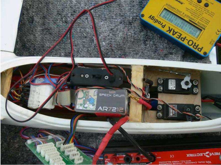
Fig. 1: An Alpina 4001 Elektro CME (a 4m motorized glider) equipped with a Crumb2560-based AR7212 is prepared for its maiden flight. Trace the satellite wires for the location of the satellites.
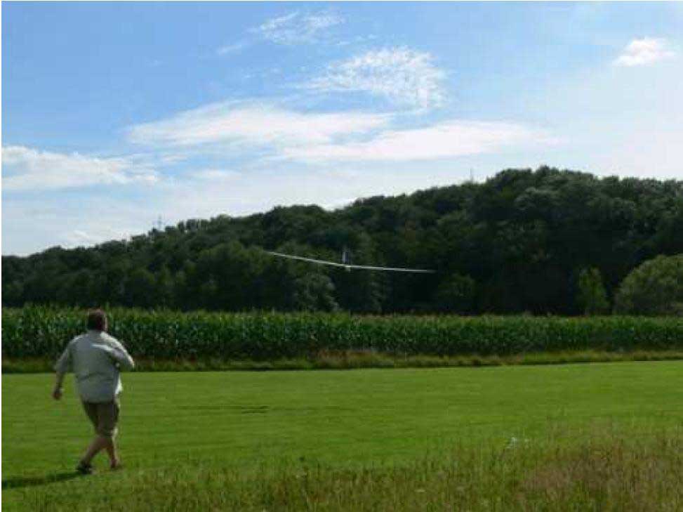
Fig. 2: Hand launching a 4m Alpina (6.5 kg) is always a thrilling exercise. Luckily it worked out not only one time: The 2009 season saw a total of 29 successful Alpina flights using the AR7212-DX7 combo. Not a single failure or malfunction during about 15 h airtime.
Programming the AR7212 via PC? How?
Connect the AR7212 to your PC via a USB (mini A) cable, switch on your plane, and start the AR7212 Programmer.
Programming begins by setting servo parameters, such as servo center, normal high, normal low, maximal high, maximal low.
Programming continues by defining 6 flight modes which are later activated by the DX7 switches GEAR and FLAP(FLTMODE/AUX1).
Flight modes may be exact copies, viz. clones, or completely independent from each other.
For each flight mode one may set up to 6x12 = 72 mixers, 12 offsets (and 12 delays, in preparation).
Five different types of mixers are available. More are planned.
So called EXPO and dual rate mixing stays programmable via the DX7 everything else is shifted to the AR7212. You are even kindly asked not to use any of the
advanced features of the DX7. Use her in basic ACRO mode -stupid as from the shelf.
After editing, the parameters are transferred to the AR7212 EEPROM by pressing the WRITE AR7212 button. They can be independantly stored on the PC disk.
Later changes to the parameter tables are easy. One may either READ AR7212 directly or take them from the disk. Edit the tables and WRITE AR7212 thats it.
Note that programming philosophy of the AR7212 makes it easy to redefine a given DX7 model to work like an as if mode 1, 2, 3, or 4 radio.
The AUX2 switch is reserved as a master control switch for later activation ofautopilot functionality.
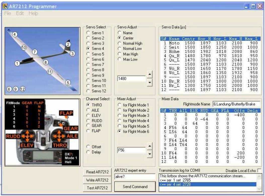
The Programmer also allows an easy uploading of firmware updates. Figure 3 gives an idea on the AR7212 programmer.
Fig. 3: A screenshot of the AR7212 Programmer
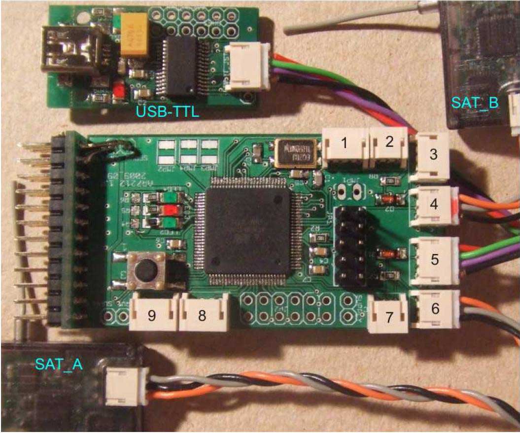
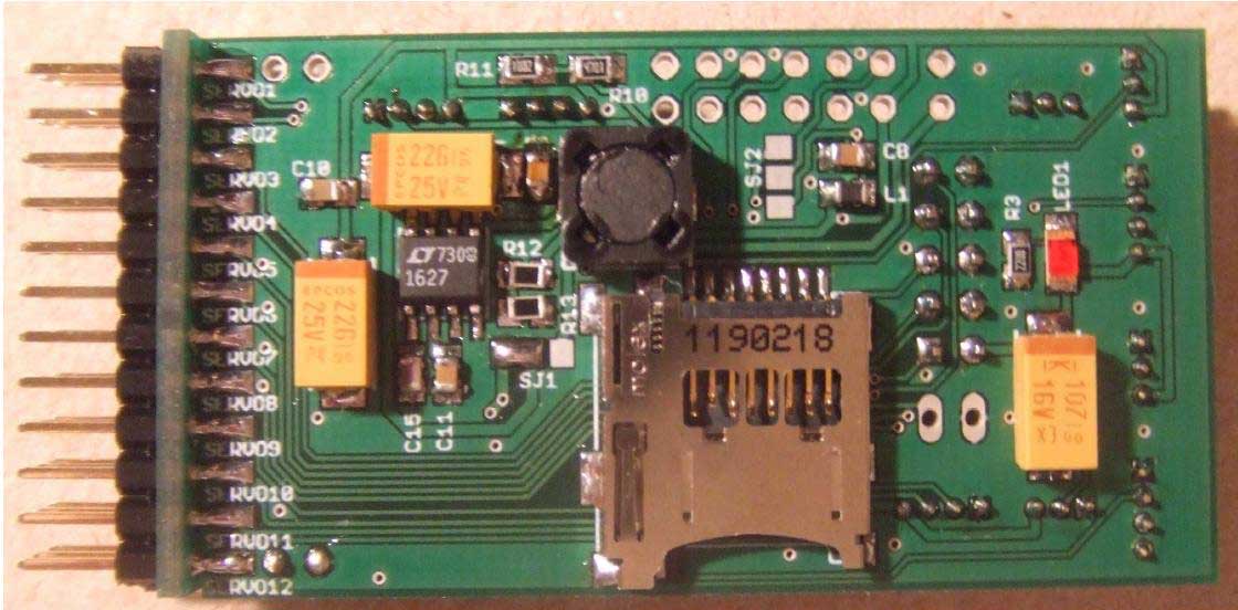
Fig. 4: The AR7212 (B revision) connected to Spektrum satellites SAT_A and SAT_B and the USB-TLL converter.
AR7212 boardsize is 60mm x 32mm. JST-ZH connectors (1)-(9) are as follows:
(1) I2C
(2) USART1 just RX (GPS)
(3) USART1 with RX and TX
(4) USART2 just RX (Satellite A)
(5) USART0 with RX and TX (USB or 2nd link (radiomodem))
(6) USART3 just RX (Satellite B)
(7) USART0 just RX
(8) 2 analog inputs (FMAdirect Copilot sensor X+Y)
(9) 2 analog inputs (Copilot sensor Z) Between (7) and (8) further analog sensors can be attached. USART0 and USART1 were equipped with both 3-pin and 4-pin connectors to be able to plug in up to 4 Spektrum satellites as an usage alternative. A servo-connector (left), a SPI/ISP header, 3 LED outputs 3 hardwirable jumpers (top, right), 1 pluggable jumper (below 1) as well as a cardholder for micro SD cards (backside) complete the connectivity of the AR7212 hardware design.
Fig. 5: (top) backside view of the AR7212_B revealing a LT1627 as low dropout regulator
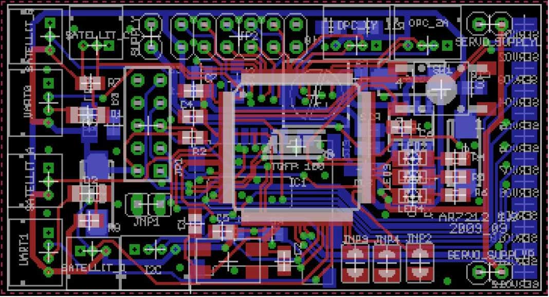
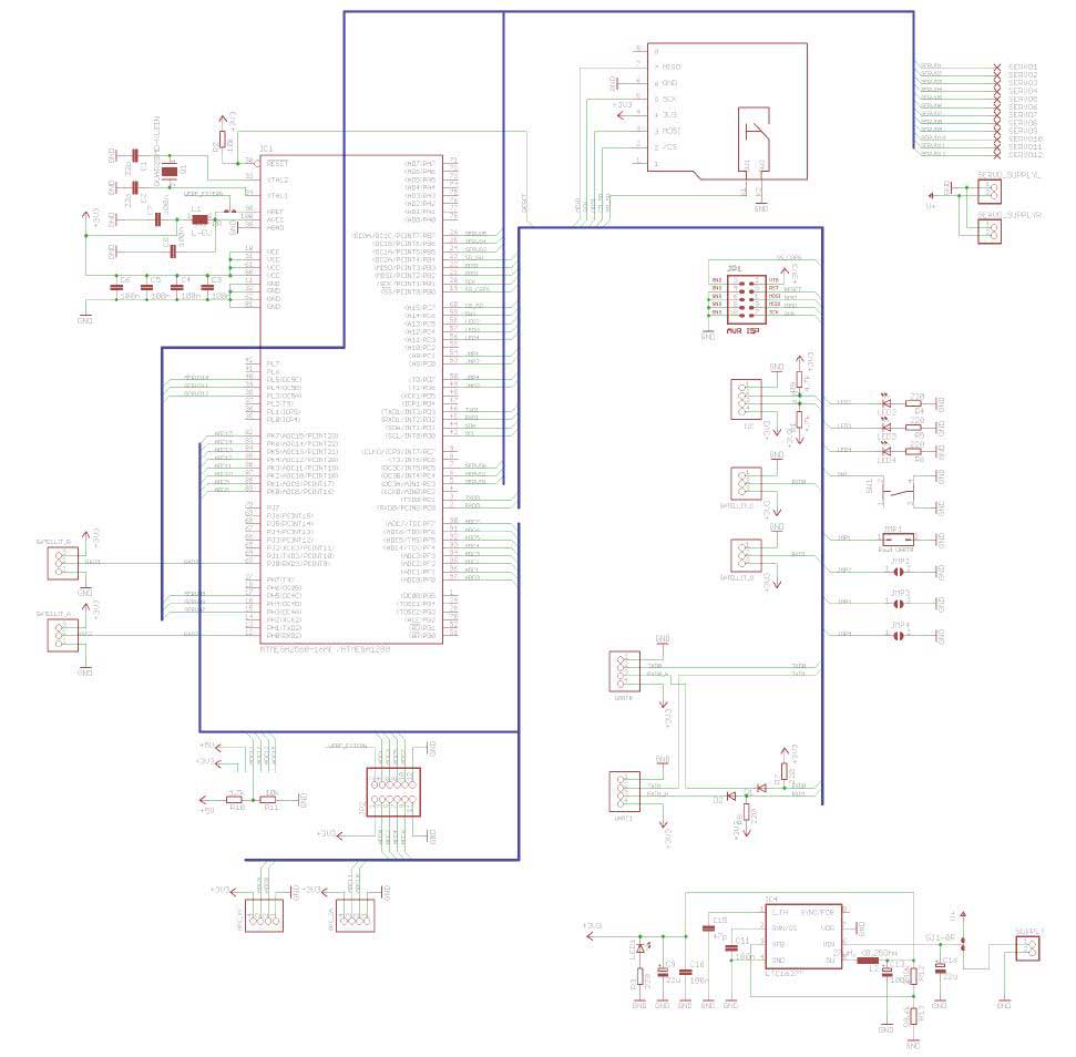
Fig. 6: Schematics of the AR7212_B
The AR7212 Hardware
While the 2009 tests were based on a commercially available module (Crumb 2560), one of us (RK) became interested to develop dedicated hardware for this project. By now three boards were developed. The first (AR7212_A) is based on the ATmega 2560 running at 14.7456 MHz instead of 16 MHz to mininimize communication errors. It requires 5V for the processor and delivers 3.3V to the satellites. It became clear that 5V electronics are becoming rare with respect to the availability of specialized components such as pressure sensors, GPS, gyros and accelerometers. Consequently the next board revision (AR7212_B, Figure 4-6) yielded a single voltage solution for 3.3 V only. We decided to select the Atmega 1280 here because it is fabricated in a more recent process. This in turn leads to a frequency voltage ramp which is obviously more tolerant toward slight overclocking. A baud quartz of 11.0592 MHz was the proper compromise between the demand for performance, the demand to minimize communication errors, and the demand imposed by the voltage frequency ramp.
Serial I/O
The Atmega 1280/2560 has four USARTS. Two of them (USART 2 and 3) are reserved for the Spektrum satellites. These fire a 16 byte serial frame at 115200 bps every 22ms. USART1 is reserved for GPS. USART0 is active while programming the AR7212 via USB cable on ground. A second purpose is to communicate with a radiomodem transmitting telemetry data while in air. For programming purposes the AR7212 is attached to a little USB TTL converter one of us (RK) has developed. The converter acts both as a USB-TTL transceiver and a 5V-3.3V level shifter.
Servos
Four16-bit timers are dedicated to the generation of rock stable (jitter-free) high resolution servo signals. The timers are operated in Fast PWM (mode 14) sending the servo pulses from all 4x3=12 output compare pins at the AT1280. Fast PWM means that the communication and computation job of the processor does not need to be interrupted when the update of the servo signals takes place. There are many ways to synthesize servo pulses and is is almost a philosophy what is best. We believe that things which can be done in the background should be done in the background. The event-system of the new line of 8-bit Xmegas is pushing forward this way of thinking: Why to disturb the workflow if the task can be handled autonomously? Sheer computation power is no means to warrant efficiency
Connectors
In addition to the servo & SPI headers (bootloader flashing) the AR7212_B has 9 receptables at the outer board (see legend of Figure 4). We saw an advantage to utilize JST-ZH connectors (also called mini JST) for all basic input/output of the AR7212 board. First of all, JST-ZH is expected to become the new standard in Micro-RC. Dedicated receivers for indoor RC are already on the market, most use JST-ZH for servo connections. 3-wire cables come with every Spektrum satellite receiver purchased. While the JST-ZH components are cheap the crimper is not. It is our hope that 4-wire mini JST cables or at least pigtails will come to the market soon: The AR7212_C is currently in the production phase it will have 4 pin connectors only.
Tips for doing things yourself
For those of you who are interested in the project and do not fear SMD soldering, the boards (AR7212_B, servo connector board, USB-TTL) needed can be ordered from any PCB shop. The AR7212zip file contains all necessary documents for a kickstart: Eagle files in the Boards directory. Components and links where to order are to be found in the Components directory. The AR7212 directory comes with the AR7212B-software (source, bin, and hex) and a dedicated bootloader (source, bin, and hex). The programmer directory contains the AR7212-programmer as executable. Sorry so far not open source presumably in the future: Please allow us to keep an eye open to industrial partnerships which do care for the needs AND the budget of RC-enthusiasts. The directory includes the official MCS-bootloader DLL, which is a special privilegue by Mark Alberts. Thanks, Mark! Files with extension DX7 hold servo and mixer data. Sample DX7 files for a Multiplex Cularis, and a Graupner/Tangent Alpina 4001 CME Elektro are included. Annotated bitmaps for these planes as well as for the DX7 model one of us owns are included as well. Other files will follow with the next AN.
Those of you who are interested but not familiar with soldering of any kind: Please indicate your interest at the Bascom AVR forum using the subject line AR7212. We need a minimum of 100 people to be able to go for a production series at low cost.
Alternatives
For those of you who never tried smt but who are familiar with a standard soldering iron (like one of us (NK;-)), there is the option to order a Crumb2560 module and to follow the instruction in the AR7212B source.
For those of you who are from the Arduino community: You may take the AR7212.hex file and use the Arduino-bootloader to flash your Arduino mega. Or you may take the AR7212B-board and develop your own Arduino-based AR7212 code. Whatever you do: We are sure that you immediately feel the difference between 8 bit PWM and 16 bit PWM, the difference between PWM and non-PWM servo signal generation (at least in a complex application) and the difference between a 5 x 10 cm form factor board and its 3 x 6 cm alternative, lately in the fuselage of your plane. The difference between Bascom and C-based platforms is so much overburdened by bullshit discussions that we can only give one advice: Do it as we do: Talents should cross-appreciate not cross-annihilate! One of us appreciates reading C but prefers to write Bascom (NK) while the other appreciates reading Bascom but prefers to write C.
Future extensions
A GPS-autopilot with telemetry and waypoint setting functionality utilizing a cellular phone link from a ground PC was developed by one of us (NK) in the years 2003-2006. It was Bascom-based and was air tested for 20h, in most cases NOT ending in a tree. Google for Speck Drum and AR7212, find a pdf and know more;-). By now this guy became a real aeromodeller he entered a club in Germany and transmuted into a soaring afficionado. So to him soaring with the birds at the edge of visibility became more attractive than looking to a screen while outdoors. Available autopilots are not really suitable for multi servo planes, as they were designed for foamies.
Clearly, improving the flight safety is a must if we consider the future of our hobby. Drone technology need to take over if we (the RC-pilots) fail in a critical situation. A major relief could come from setting a switch that brings us either home or into safe zone when such critical situation happens. This is the direction the AR7212X extensions will address. It is not intended to support the age-old dream of unlimited flight, which today is even kind of easy by cellular phone technology and GPS. AR7212X users are happy and feel obliged to follow the visual flight rules as any other small aircraft pilot or RC-pilot is happy to obey.
The basic hardware of the AR7212X will be identical to the AR7212_B board. In addition to the flight stabilisation via IR-sensors (CPD-4) the AR7212X will offer support for the new generation of 6DOF AHRS modules announced by CH robotics for February 2010.
A final remark
Please do not direct technical or availability-based questions to our email addresses please post these questions into the Bascom AVR forum using AR7212 in the subject line. This way it will save time and help more efficiently.
Snapshot of source code (complete source code is not shown because it is too long for publishing, full code you can find in ZIP archive above)
'@@@@@@@@@@@@@@@@@@@@@@@@@@@@@@@@@@@@@@@@@@@@@@@@@@@@@@@@@@@@@@@@@@@@@@@@@@@@@@@
'@@@@@@@@@@@@@@@@@@@@@@@@@@@ @@@@@@@@@@@@@@@@@@@@@@@@@@@@@
'@@@@@@@@@@@@@@@@@@@@@@@@@@@ [Speck Drum AR7212] @@@@@@@@@@@@@@@@@@@@@@@@@@@@@
'@@@@@@@@@@@@@@@@@@@@@@@@@@@ by Kiedro 2009-2010 @@@@@@@@@@@@@@@@@@@@@@@@@@@@@
'@@@@@@@@@@@@@@@@@@@@@@@@@@@ @@@@@@@@@@@@@@@@@@@@@@@@@@@@@
'@@@@@@@@@@@@@@@@@@@@@@@@@@@@@@@@@@@@@@@@@@@@@@@@@@@@@@@@@@@@@@@@@@@@@@@@@@@@@@@
'
'Brief legal notice: No responsibility is taken by the author whether the software
'is operative and applied in a legal and peaceful context. The author appreciates
'a notification of bona fide applications at Natalius (without space) 272 (at)
'yahoo (dot) de. For commercial applications: Contacting the author is a must.
'
'Please direct technical questions on the software and hardware of this project
'to the Bascom AVR forum at MCS Electronics. Always use the term AR7212 in the
'subject line of your contribution. I'm happy to help (if I can) - things are
'at the forum however.
'
''----------------------------------[Purpose]-----------------------------------
''An Atmega 1280/2560 takes the input from 2 Spektrum Remote Receivers (satellite
''receivers bound to a single DX7 radio before) to compute 12 servo output channels
''at high resolution (16 bit fast PWM).
''The DX7 may be used "off the shelf". After having entered the model name, set it
''to basic ACRO. No further programming is required. All intelligence
''is onboard, and all programming (servo center position, servo travel limiters,
''mixer adjust) is done with the help of the AR7212 programmer, a PC program con-
''nected to the board via USB while on ground. EXPO and DUAL RATE functions may
''however be set on the DX7.
''As the code for Speck Drum AR7212 was developened from what I call Cell-RC project
''the board software can be expanded to act as a UAV GPS autopilot sending and
''receiving data to a ground station either via GSM or via a 433 MHz ISM link.
''These extensions will be the subject of a future application note at MCS.
''
''--------------------------------[Applications]--------------------------------
''Large full-house RC sailplanes and motorized aircrafts with 7-12 servo channels
''required. FPV controlled RC planes with 5.8 GHz equipment. Robotic applications of
''Spektrum radio links. UAV applications based on Spektrum radio links.
''
''----------------------[Development boards and clock speed]--------------------
''Note that the AR7212 has been implemented using a number of different boards.
''The original design is based on a commercially available module (Crumb2560)
''connected to a breadboard servo connector via flat ribbon cable. It needs both,
''5V for the 2560 and 3.3V for the Spektrum satellite receivers. The Crumb2560-
''based AR7212 runs with 14.7456 MHz clock speed and has been tested in the air
''for more than 15 hours using a motorized Tangent Alpina 4001 CME. No failure or
''malfunction during 29 flights in the 2009 season. Soldering instructions can
''be found below, no Autopilot extensions however.
''Three AR7212 boards for Autopilot entensions were developed by Ralf Kull. The
''first (AR7212_A) is a two voltage solution providing the 3.3 V exclusively to
''the Spektrum satellites, while operating the ATmega 2560 at 14.7456 MHz and 5 V.
''The 2nd board (AR7212_B) is a single voltage solution which provides 3.3V to
''all external and onboard components. The board allows JST-ZH connector plug-in
''for 2 Spektrum satellites, GPS, a 2nd link, 2 FMA Copilot CPD4 IR-Sensors, and
''further analog sensors. It is based on the Atmega 1280 running at 11.0592 MHz
''clock speed, viz. slightly overclocked. While the clockspeed-voltage ramp of
''the 2560 allows frequencies above 8 MHz at 5V only, the 1280 benefits from a
''later fab process resulting in a more flexible frequency voltage ramp.
''Thus slight overclocking is expected to be "in range" for almost any 1280 chip
''brought to the market today. We nevertheless recommend to do extensive air
''tests on planes of the MPX-Cularis class before moving to advanced platforms.
''NOTE THAT AR7212_B IS DESCRIBED IN THE APPLICATION NOTE 17.. AT MCS ELECTRONICS.
''The latest board (RX-12) is a redesign of AR7212_B with respect to the port
''assignments, the voltage regulator, the servo connector and JST-ZH plug in. The
''board does not anymore allow direct plug-in of Spektrum satellites and is meant
''to serve as a platform for those who would like to adopt the software for non-
''Spektrum based satellites.
''An AR7212 based on the Xmega128A1 is currently in development.It makes use of
''a commercially available module (Xmega-A1-USB). The code for the Xmega below is
''currently only operative for servo PWM synthesis. Support for high speed UART
''communication will be added later once serial ring buffers are supported by Bascom.
'!!!!!!!!!!!!!!!!!!!!!!!!!!!!!!!!!!!!!!!!!!!!!!!!!!!!!!!!!!!!!!!!!!!!!!!!!!!!!!!
'!!!!!!!!!!!!!!!!!!!!!!!!!!!!!!!!!!!!!!!!!!!!!!!!!!!!!!!!!!!!!!!!!!!!!!!!!!!!!!!
'!!!!!!!!!!!!!!!!!!!!!!!!!!!!!!!!!!!!!!!!!!!!!!!!!!!!!!!!!!!!!!!!!!!!!!!!!!!!!!!
' =====================> SET UP THE BOARD AND CRYSTAL HERE <====================
' ===================> THIS IS THE ONLY THING YOU NEED TO DO <==================
'}
|