,,It is a simple and low cost system which
comprises a small transmitter which attaches to the animals collar, a
hand held receiver and a simple home made 3 element Yagi directional
antenna,,
by Don Owen ( dono2 at tpg dot com dot au )
This radio tracker on 433MHz was made
to locate our cat which goes walkabout in the neighborhood but can be
used for other pets such as dogs. Its range is only about 50 to 100 meters which is sufficient as cats usually have hiding places usually
fairly close to their homes. It is a simple and low cost system which
comprises a small transmitter which attaches to the animals collar, a
hand held receiver and a simple home made 3 element yagi directional
antenna. There has been no attempts to optimize the hardware or
software and improvements could certainly be made using a more
directional antenna as well as optimizing software parameters. The
most difficult part is to find a suitable enclosure to house the
small transmitter and this has still not been fully solved. The
person with the hand held receiver and antenna hears a repetitive
audio beep in the headphones about every 800mS if the animal is
within range as well as observing the signal strength on the LCD. By
pointing the antenna in the animals direction, the signal strength
will increase and location can be made.
Transmit unit:
A commercially
available Transmit module TXC1 has its data input pin fed via an IC
pulse generator causing it to give a small burst of carrier for about
8mS every 800mS. The small duty cycle is used to reduce battery drain
from the 3V lithium cell. A short length of wire following the
contour of the collar is used as the transmit antenna.
The Tx uses a Lithium 3V cell rated at 210mAH and the Tx draws around 0.25mA which gives about 840 hours. 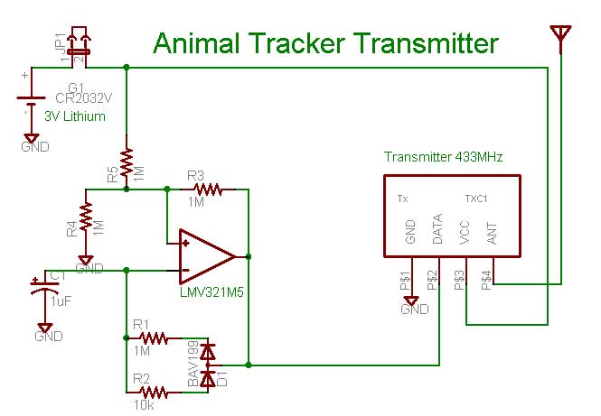
Receive unit:
The commercially
available Receive module RXB1 uses the RX3400 chip and this has to be
modified so that pin 22 is brought out to feed an ATMega8535 A/D
input. The continuously converting A/D reading is used whenever the
timer interrupts. If there are two contiguous readings that are
above the software set threshold, then their values are averaged and
displayed on the LCD to show the received signal strength and this is
accompanied by an audio beep in the headphones. The repetition rate
of the interrupt process determined by the timer must fit at least
two readings inside the 8mS slot where there is carrier. This carrier
width (determined by the Transmitter), the timer period and the
threshold are parameters that can be played with for optimization
purposes. 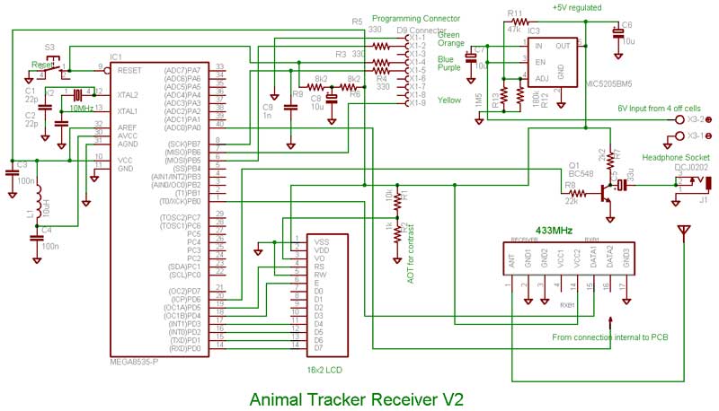
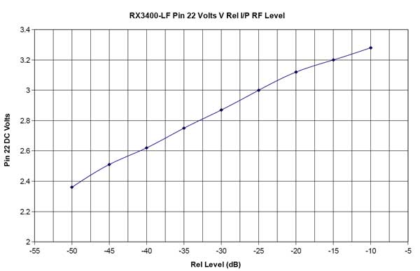
Relationship between signal strength and DC level on pin 22 of the receiver module
Source code:
' Program Animal tracking receiver
' Don Owen Dec 16 2009 AnimalRx.bas
'--------------------------------------------------------------
'**********************************************************************
'** Information and Calculations **
'**********************************************************************
'This works in conjunction with the TXC1 Transmitter module which is arranged
'to give a small burst of carrier for approximately 8mS every 800mS.
'This Rx continually samples the level on pin 22 of the RX3400 chip which is
'part of the RXB1 receiver module. Note that pin 22 is not brought out to a
'connection pin on the module.
'The level is read every 3mS which is determined by the timer generated
'interrupt. If 2 consecutive readings are above the software chosen threshold
'level then the LCD shows the received carrier level and as well as generating
'a small tone burst which is fed to an earpiece or headphones.
'Because there is only an 8mS period where the carrier is present, two samples
'taken approximately 3mS apart will fit into this period. All other samples
'will not find a carrier until the next carrier burst 800mS later.
'NOTES:
'A/D conversion takes slightly over 1ms
'The timer workings are as follows
'Times/sec to overflow (TOV) =Xtal freq/(Pscale * 2^16). If xtal is 10000000
'and Pscale is 1024 then TOV = 6.71 sec.
'Now the time for each count is 6.71/2^16 = 0.0001024 Sec.
'For a 3mS overflow
'so it will take 0.003/0.0001024 = 30 counts to equal 3mS.
'Therefore Preload = MaxCountOfTimer - 30
' = 65536 - 30
' = 65506
'**********************************************************************
'** Define working variables and constants **
'**********************************************************************
$regfile = "m8535.dat" 'Uses ATMega8535
$crystal = 10000000 'timing is dependent on this clock
Dim Rxlevel As Word 'value for measured a/d i/p level
Dim Rxlevel_old As Word
Dim Count As Integer
Dim High_level_flag As Boolean
Dim I As Integer
Const Sample_time = 65506 'count to this value for 3mS
Const Threshold = 444 '2.4 volts at pin 22 of RX3400
Const Max_count = 1000
'**********************************************************************
'** Declare subroutines and functions **
'**********************************************************************
'
Declare Sub Receive_ok
'**********************************************************************
'** Start Main Program **
'**********************************************************************
Cls
Config Portd.6 = Output
Config Lcd = 16 * 2
Config Lcdpin = Pin , Db4 = Portd.3 , Db5 = Portd.2 , Db6 = Portd.1 , Db7 = Portd.0 , E = Portd.4 , Rs = Portd.5
Cursor Off 'no lcd cursor
Config Adc = Single , Prescaler = Auto 'adc config
Start Adc
Config Timer1 = Timer , Prescale = 1024 'timer config
Timer1 = Sample_time
On Timer1 Timer1_isr
Enable Timer1
Enable Interrupts
Upperline
Lcd "Animal Tracker" 'display call/date
Lowerline
Lcd "AnimalRx.bas" 'displays filename
Wait 3
Cls
Start Timer1
Reset High_level_flag
Count = 0
Lcd "No Signal"
Do 'Loop until timer 1 interrupts
Loop
End
'**********************************************************************
'** Define Subroutines **
'**********************************************************************
'This sub outputs the received level to the LCD as well as generating a
'tone burst.
Sub Receive_ok
Cls
Lcd "I/P level = " ; Rxlevel
For I = 1 To 80 Step 1 'gives tone burst on portd.6
Set Portd.6
Waitms 1
Reset Portd.6
Waitms 1
Next I
Reset High_level_flag
Count = 0
Waitms 500
End Sub
'**********************************************************************
'** Define ISR **
'**********************************************************************
'When timer causes an interrupt, the ADC value is retrieved and this then
'decides what action is required.
Timer1_isr:
Stop Timer1
Rxlevel = Getadc(0) 'get A/D level value
If Rxlevel < Threshold Then Goto Refresh
If High_level_flag = 0 Then Goto First_high_level
Rxlevel = Rxlevel_old + Rxlevel 'obtain average level
Rxlevel = Rxlevel / 2
Receive_ok
Goto Resume
First_high_level:
Rxlevel_old = Rxlevel
Set High_level_flag
Refresh:
If Count < Max_count Then Goto Resume
Cls
Lcd "No signal"
Count = 0
Resume:
Incr Count
Timer1 = Sample_time
Start Timer1
Return |


