by Don Owen
The purpose of this system is to check the
range and reliability of low powered radio links. The Transmit unit comprises a
Mega8515 micro, a Holtek encoder chip
HC12E and an RF module ZW3100 TX
(433.92MHz). However, virtually any RF Transmit module can be substituted here
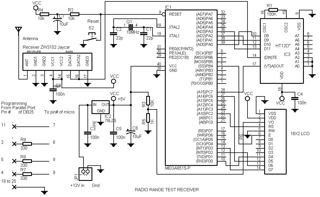
as long as it is compatible with its corresponding receiver. The Receive unit
comprises a Mega8515 micro, a Holtek decoder chip HC12D and an RF module ZW3102
Rx (433.92MHz). The system operation is usually arranged to have a fixed
location for the Transmit unit while the Receive unit is moved around until
data is no longer reliably received. For low power units a reliable range is
typically a little over 100 meters.
Transmit unit:
This is arranged to output a pulse from a
port on the Mega8515. The pulse occurs once every 5 sec and lasts for 0.5 sec.
A mark/space ratio of 9:1. This pulse activates the HC12E to output data in the
0.5 sec interval, which in turn modulates the ZW3100 Transmitter.
Receive unit:
The ZW3102 in the receive unit outputs the
demodulated data for decoding by the HC12D which when successfully decoded
produces a momentary high level from the decoders VT pin as well as latching
the 4 data bits. These 5 lines are then fed to the Mega8515 for processing and
the result is displayed on the LCD which shows a good/bad count as well as the
data corresponding to the 4 data lines in decimal form (0 to 15). Timing is
under the control of the Mega8515. The addresses for the encoder and decoder
must be the same. The circuits of the Transmit and Receive units show the
addresses hard wired for simplicity, as are the 4 data lines.
Operation:
The transmit and receive units are placed
near each other for synchronizing purposes as there will be no good/bad count
displayed until this occurs. The portable receive unit is then progressively
moved away from the transmit unit until bad counts are displayed by the LCD.
The actual data value as per the value in the hard-wired transmit unit is also
displayed.
Other aspects:
Further enhancements to this system could
be made by using a piezo buzzer connected to a Mega8515 port and programmed to
produce a sound when a good pulse is received. As the system was made up
using boards that were previously used for other purposes, the micro connection
groupings probably appear strange. The programming may appear to be a little
clumsy by experienced programmers standards but the system as described proved
to be very reliable.
|