Anatoly A. Tokarev, Russia, 2007
That was got as a result:
4 channels of the regulation;
the regulation of the output voltage from 0 before
practically 12 In
stair, 128 stairs of the regulation;
the regulator is executed on scheme SEW so in it
nothing do not get-warm (at least once so that there was it is necessary to put
the radiators);
the frequency SEW 31250 Hz - an ultrasonic range - so
works noiseless, no snub ;
after enabling rheobas (the computer) for 10 seconds
occurs spinup ventilator on maximum voltage (12 volts), simultaneously occurs observation
maximum velocity of the rotation impeller ventilator;
after spinup voltage in channel is fixed such, what it
was under the last regulation and rheobas moves over to operating duty;
the speed measurements of the rotation impeller
ventilator occurs round-robin, in 2 seconds is chosen next channel, is measured
velocity, results of the measurement are removed on screen in the manner of
absolute importance (in rotation per minute) and in the manner of percent from
maximum velocity;
if the impeller cost(stand)s (no tahoe a signal), is
removed report on damages on indicator and is given bleep (the amount
"cheep" corresponds to the number of the channel, in which has
occurred the damage);
the channel possible to switch off, bring level of the
output voltage before 0, herewith it will not be interviewed, but on screen is
removed message "out-of-work".
As it is seen, scheme became greatly in contrast with
previous variant more simply. Do Not think that one more alteration will allow
to do rheobas in 2 resistors :).
Some explanations to scheme:
the microcontroller DD1 forms 4 SEW the signal for
governing P-canal MOSFET key DA1, DA2;
for clock microcontroller is used internal generator 8
MHZ, this has allowed to free the vapour a conclusion (for possible hereinafter
connections sensor temperature) and reduce the price of the scheme;
information about the work channel regulations is
removed on two-row ZHK indicator HL1, information in indicator is sent on quad
bit to bus;
the buttons S1-S3 control work of rheobas, capacitors
S2-S4, included parallel button, are intended for suppression bounce, are used
internal tightening resistors on conclusion of the microcontroller, to which is
connected buttons;
the chain R9,C5 and internal tightening resistor of
the microcontroller execute the function of the voltage level co-ordination
and, simultaneously, function of the filter of the low frequency, suppressing
to a certain degree short pulsed hindrances in tahoe a signal ventilator;
for relief of searching for radio elements, the
co-ordination level voltages of the microcontroller and MOSFET of keys are
executed otherwise, than in previous scheme: instead of microcircuit of the
co-ordination level 74F07, is used other scheme of the feeding (the stabilizer
of the negative voltage DA3) with the result that findings Vcc microcontroller
and Vdd indicator are connected to voltage +12 В, but findings GND microcontroller and Vss indicator
are connected to voltage +7 In
(leaving the stabilizer DA3). The Voltages are brought to the general wire (the
body) of the computer feeding.
Such decision aside from plus (the stabilizer 79L05 to
find greatly more simply, than 74F07), has and negative side: printed charge
and particularly indicator it is necessary to fix so that was not a contact no
their current-carrying parts (the conductor, platform, frames of the indicator
etc.) with body of the computer!
Management:
S1 - "less", reduces the voltage on
ventilator;
S2 - "fix", fixes the current channel,
triangle appears left of inscription "Channel", the repeated striking
removes fixing the channel, they will newly be switched in 2 seconds;
S3 - "more", enlarges the voltage on
ventilator.
simultaneous striking S1+S3 - an unset rheobas, is
newly produced spinup of impeller and measurement to maximum velocity of the
rotation.
Long striking on button (long 1 seconds) includes auto
cycling.
Now about
designs: this variant, either as
previous rheobas, am going to to place in compartment 3,5" so as constructive
I have taken the old spindle 3,5", has thrown whole stuffing, has sawed;
sawn off the spare glandules and from face plastic panel has left only frame:
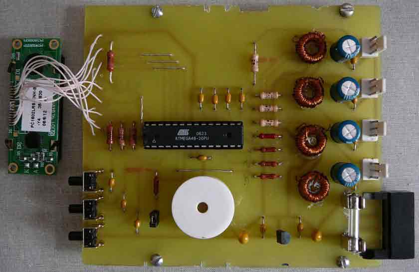
We Assemble the elements (DA1, DA2 - on the part of
conductor!), throttles L1-L4 crepe on charge hot melt, solder the indicator.
On charge, beside connector of the connection of the
feeding, is installed fusible fuze in chain of the general wire ventilator,it,
certainly, possible change the jumper, however better his(its) put(deliver) to
under casual closing conclusion 1,2
in connector XP1-XP4 not to burn the keys DA1, DA2. I
was lazy immediately its put(deliver), as a result happened to to change the
burned; burned microcircuit DA2.
For fastening the charge 4 screws M3 we use to constructive,
it is necessary to take not too long - that they did not protrude from below -
and, in ditto time that their lengths have been enough for installing plastic little
buildings, raising slightly charge from constructive. This will allow align
position of the buttons by the vertical.
The Indicator while (for time first experiment) shall
bolt hot glue.
Programming the microcontroller:
Categorically it is impossible programmer the
microcontroller, stated in board of
rheobas and eating from this computer - possible all пожечь!
Without fall programmer the microcontroller or in
industrial programmator, or if it homemade and is intended for in-circuit of the
programming, connect to it panel for
installing the microcircuit.
The Regulation:
Single that can require the regulations, this
adjustment contrast scenes on indicator. For regulation change the chain a
resistor R3, R4 on variable (preset) resistor 10 lumps, extreme findings of the
variable resistor connect to chain +12 В and +7 В, but average output (the crawler) to
output 3 indicators. Approaching scenes, on indicator. Unsolder resistor from
board. To make size, resistances shoulder variable resistor (from average
output before extreme outled) and install the constant resistors such or close
nominal value.
No more regulations rheobas require.
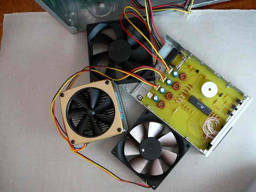
We Proceed with experiment.
We Connect the ventilators and feeding, in channel 4
ventilators do not include:
After enabling (or after simultaneous striking the
buttons S1, S2), during of the spinup.
Indication of
velocities in channel in rotation per minute and percent from maximum
velocity.
In channel 4
ventilators was not connected so signal is removed about damages.
The Channel
possible to switch off, for this it is necessary to reduce the voltage before
0.
As a matter of
convenience regulations, channel, in which goes the regulation possible to fix
striking the button S2 If install too small voltage on ventilator, tahoe a
sensor can give the wrong signal, as a result of evidences speed will be
distant from reality.
The Practical advice: undesirable to install the
velocity of the rotation below 30% from maximum, many ventilators in this case
give the sloppy tahoe a signal.
Remained invent form and highly of the buttons, neatly
do the front panel from stub. But this I will concern this at May.
For interesting persons to repeat rheobas, are
enclosed:
the drawing of the printed board (ready to use on
lazer-ironing to technologies);
the picture with location element on printed board;
the lace trim of the microcontroller;
the primaries. Schematic:
Constrution examples:
Source code:
'===============================================================================
'
' 4 channel PWM rheobus for computer's fans on ATMega48.
'
' Rheo200Le.bas
'
' (c) Anatoly A. Tokarev 2007, atlab@zmail.ru
' NOT FOR COMMERCIAL USE!
'
' This is my first project on Atmel's microcontroller.
' It was started on 26 march 2007 and was fully (with hardware
' making and debugging) completed on 19 april 2007
' THANKS TO THE BASCOM-AVR.
'
'===============================================================================
'
' Design features:
' - internal ATMega RC generator 8 MHz
' - 4 PWM channels (regulation and measurement)
' - PWM is in ultrasound range (no sounds or clicks)
' - 0V <= Vout <= 12 V
' - 3 button user control
' - 2*16 LCD (# channel, fan speed: rpm and percentage of max speed)
' - 10 sec. full speed spinup after power on
'===============================================================================
'
'-- Control --------------------------------------------------------------------
' - button "Right" - increase fan speed
' - button "Left" - decrease fan speed
' - button "Center" - select # fan
' - buttons "Left+Right" - soft reset
'
'-- LCD ------------------------------------------------------------------------
' Db4 - PortC.0
' Db5 - PortC.1
' Db6 - PortC.2
' Db7 - PortC.3
' E - PortC.4
' Rs - PortC.5
'
'-- PWM outputs ----------------------------------------------------------------
' 5 - OC2B/PD3 - Pwm4
' 11 - OC0B/PD5 - Pwm2
' 12 - OC0A/PD6 - Pwm1
' 17 - OC2A/PB3 - Pwm3
'
'-- FAN tach -------------------------------------------------------------------
' 15 - PortB.1 - Tach1
' 16 - PortB.2 - Tach2
' 18 - PortB.4 - Tach3
' 19 - PortB.5 - Tach4
'
'-- Buttons --------------------------------------------------------------------
' Left (Key1) - PinD.0
' Center (Key2) - PinD.1
' Right (Key3) - PinD.2
'===============================================================================
$regfile = "m48def.dat"
$crystal = 8000000
'-- Timers init ----------------------------------------------------------------
'TMR0 and TMR2 use FAST PWM mode
Tccr0a = &HF3
Tccr0b = &H01
Tccr2a = &HF3
Tccr2b = &H01
' TMR1 used for fan failure check
Config Timer1 = Timer , Prescale = 64
'-- Ports init -----------------------------------------------------------------
Config Portb = &B11001001 'PB1,2,4,5 outputs, other - inputs
Portb = &B00110110 'use pullup on inputs
Config Portc = &B10111111 'PŃ6 - input
Portc = &B01000000 'use pullup on inputs
Config Portd = &B11101000 'PD0,1,2,4 - inputs
Portd = &B00010111 'use pullup on inputs
'-- LCD config ------------------------------------------------------------------
Config Lcdpin = Pin , Db4 = Portc.0 , Db5 = Portc.1 , Db6 = Portc.2 , Db7 = Portc.3 , E = Portc.5 , Rs = Portc.4
Config Lcd = 16 * 2
'-- Buttons config -------------------------------------------------------------
Key1 Alias Pind.0 ' âëĺâî
Key2 Alias Pind.1 ' öĺíňđ
Key3 Alias Pind.2 ' âďđŕâî
'-- Alarm zummer ---------------------------------------------------------------
Speaker Alias Portd.4 '
'-- Variables ------------------------------------------------------------------
Dim T1over As Bit ' flag, if Timer1 is overflowed, whis is fan failure
Dim Needshow As Bit ' flag, need to show rpm
Dim Needtosave As Bit ' flag, need to save data in EEPROM
Dim Fixnchan As Bit ' flag, # channel is fixed
Dim Key1pressed As Byte '
Dim Key2pressed As Bit '
Dim Key3pressed As Byte '
Dim Cntr As Byte ' counter
Dim Ptr As Byte ' pinter
Dim Q(4) As Byte ' relative pulse duration
Dim Nchan As Byte ' # selected channel
Dim Nc As Byte
Dim Pcintcntr As Byte ' counter for 1/2 revolution
Dim Perc As Word '
Dim I As Byte '
Dim J As Byte '
Dim K As Byte '
Dim Pixelprogress As Word
Dim T1 As Word ' TMR1 save buffer
Dim Nmax(4) As Word '
Dim N(4) As Word '
Dim Nl As Long ' speed, rpm
Dim Buf As Word
Dim W As Word
Dim Nchstr As String * 1
$eeprom ' preprogrammed speed
Data 32 , 64 , 128 , 196
$data
'-- Interrupts -----------------------------------------------------------------
On Pcint0 Isr_pcint0 ' PortB pin change interrupt (from fans)
On Ovf1 Isr_tmr1 '
'-- Begin ----------------------------------------------------------------------
Progstart: ' soft reset label
Pcmsk0 = 0 '
Timsk = 1 '
Disable Pcint0
Stop Timer1
Disable Timer1
Pwm0a = 255
Pwm0b = 255
Pwm2a = 255
Pwm2b = 255
'-- User defined symbols in LCD ------------------------------------------------
'-- Progressbar ----------------------------------------------------------------
Deflcdchar 0 , 32 , 32 , 32 , 32 , 32 , 32 , 32 , 32 '
Deflcdchar 1 , 16 , 16 , 16 , 16 , 16 , 16 , 16 , 16 '
Deflcdchar 2 , 24 , 24 , 24 , 24 , 24 , 24 , 24 , 24 '
Deflcdchar 3 , 28 , 28 , 28 , 28 , 28 , 28 , 28 , 28 '
Deflcdchar 4 , 30 , 30 , 30 , 30 , 30 , 30 , 30 , 30 '
Deflcdchar 5 , 31 , 31 , 31 , 31 , 31 , 31 , 31 , 31 '
'-- Right triange --------------------------------------------------------------
Deflcdchar 6 , 16 , 24 , 28 , 30 , 30 , 28 , 24 , 16 '>
Cls
Cursor Off Noblink
Upperline
Lcd "Rheobus v2.00Le "
Lowerline
Lcd "(c) 2007 ATLab "
Waitms 10000 ' 10 sec. spinup
Needshow = 0
Enable Interrupts
For Nchan = 1 To 4 Step 1 ' read PWM presets
Ptr = Nchan + 8
Readeeprom Q(nchan) , Ptr
Gosub Speedmeter ' Max speed measurment
Waitms 500
If Needshow = 1 Then
Gosub Calcspeed
Nmax(nchan) = Nl '7500000 T1
Needshow = 0
Else
Nmax(nchan) = 0
End If
Next Nchan
Pwm0b = Q(1) ' set PWM
Pwm0a = Q(2)
Pwm2a = Q(3)
Pwm2b = Q(4)
Waitms 2000 ' 2 sec. for spin stabilization
Nchan = 4
Cntr = 3
T1over = 0
Needshow = 0
Needtosave = 0
Fixnchan = 0
Key1pressed = 0
Key2pressed = 0
Key3pressed = 0
'-- Endless loop ---------------------------------------------------------------
Do
' buttons 1,3 check pressed
If Key1 = 0 Or Key3 = 0 Then
' 1,3 pressed simultaneously
If Key1 = 0 And Key3 = 0 Then
Goto Progstart ' soft reset
End If
' if pressed 3 (Right), increase rpm
If Key3 = 0 Then '
If Key3pressed < 5 Then '
Key3pressed = Key3pressed + 1 ' autorepeat after 1 sec
End If
If Key3pressed = 1 Or Key3pressed => 5 Then ' first press and autorepeat
If Q(nchan) => 254 Then
Q(nchan) = 255
Else
Q(nchan) = Q(nchan) + 2
End If
End If
Else
Key3pressed = 0 ' flag clear if button isn't pressed
End If
' if pressed 1 (Left), decrease rpm
If Key1 = 0 Then '
If Key1pressed < 5 Then '
Key1pressed = Key1pressed + 1 ' autorepeat after 1 sec
End If
If Key1pressed = 1 Or Key1pressed => 5 Then ' first press and autorepeat
If Q(nchan) <= 2 Then
Q(nchan) = 0
Else
Q(nchan) = Q(nchan) - 2
End If
End If
Else
Key1pressed = 0
End If
' setup PWM
Pwm0b = Q(1)
Pwm0a = Q(2)
Pwm2a = Q(3)
Pwm2b = Q(4)
Cntr = 0
Needtosave = 1
' RPM measurement after speed change
If Q(nchan) = 0 Then
Gosub Showfan
Else
Gosub Speedmeter '
End If
Else
Key1pressed = 0
Key3pressed = 0
End If
' check button 2 (center) pressed
If Key2 = 0 Then ' select (fix) cahnnel
If Key2pressed = 0 Then
Key2pressed = 1
Locate 1 , 1
If Fixnchan = 0 Then
Fixnchan = 1
Lcd Chr(6) ' >
Else
Fixnchan = 0
Lcd " "
End If
End If
Else
Key2pressed = 0
End If
' pause 0.25 sec for the process sync.
Waitms 250
Cntr = Cntr + 1
' 0.5 sec later button release: save PWM data in EEPROM
If Needtosave = 1 Then
If Cntr => 2 Then
Writeeeprom Q(1) , 9
Writeeeprom Q(2) , 10
Writeeeprom Q(3) , 11
Writeeeprom Q(4) , 12
Needtosave = 0 '
End If
End If
' next channel measerement after 2 sec.
If Cntr => 8 Then '
Cntr = 0
If Fixnchan = 0 Then
Nchan = Nchan + 1 ' select next channel:
If Nchan > 4 Then ' 1->2->3->4->1..
Nchan = 1 '
End If
End If
If Q(nchan) = 0 Then
Gosub Showfan
Else
Gosub Speedmeter ' measurement
End If
End If
If Needshow = 1 Then ' Measurement executed
Gosub Calcspeed ' Calculate the rpm
N(nchan) = Nl '
If N(nchan) > Nmax(nchan) Then
Nmax(nchan) = N(nchan)
End If
Gosub Showfan ' and show on LCD
Needshow = 0
End If
' time is over, this is fan failure
If T1over = 1 Then
Gosub Showfan ' show on LCD
T1over = 0
End If
Loop
'-------------------------------------------------------------------------------
'===============================================================================
' Show results on LCD
Showfan:
'-------------------------------------------------------------------------------
Nc = Nchan + 48 ' for ROM economy
Nchstr = Chr(nc) '
Cls
Locate 1 , 1
If Fixnchan = 1 Then
Lcd Chr(6) '"{201}" (like ">" sign)
Else
Lcd " "
End If
Locate 1 , 2
Lcd "Channel" ' channel
Lcd Nchstr ' number
If Q(nchan) = 0 Then
Lcd " is OFF " '
Else
If T1over = 1 Then
Lcd " ALARM! " '
For I = 1 To Nchan ' make sound
For W = 600 To 300 Step -4
Sound Speaker , 5 , W '
Next J
Waitms 200
Next I
Else
Lcd " "
Lcd Str(n(nchan)) ' RPM
Lcd " rpm" '
Perc = N(nchan) * 10 ' calc percentage of Max Speed
Pixelprogress = Perc
Buf = Nmax(nchan) 10
Perc = Perc Buf
Locate 2 , 2 ' show %
Lcd Str(perc)
Lcd "% "
Buf = Nmax(nchan) 5
Pixelprogress = Pixelprogress Buf ' Nmax(nchan)
Locate 2 , 6 ' show progress bar
For I = 0 To 9 Step 1
J = I * 5
K = J + 5
If K > Pixelprogress Then
If J > Pixelprogress Then
Ptr = 0
Else
Ptr = Pixelprogress Mod 5
End If
Else
Ptr = 5
End If
Lcd Chr(ptr)
Next I
End If
End If
Return
'===============================================================================
'===============================================================================
' Speed calculation
Calcspeed:
'-------------------------------------------------------------------------------
Nl = 7500000 T1
Return
'===============================================================================
'===============================================================================
' Speed measurement start
Speedmeter:
'-------------------------------------------------------------------------------
If Q(nchan) = 0 Then ' if channel is Off, no measure
Return
End If
Pcintcntr = 0
Timer1 = 0
T1 = 0
Start Timer1
Select Case Nchan '
Case 4
Pcmsk0 = &B00100000 ' interrupt mask for Tach4
Case 3
Pcmsk0 = &B00010000 ' interrupt mask for Tach3
Case 2
Pcmsk0 = &B00000100 ' interrupt mask for Tach2
Case 1
Pcmsk0 = &B00000010 ' interrupt mask for Tach1
End Select
Waitus 5 '
Pcifr = 0 ' clr flag
Enable Pcint0 ' enable interrupts
Enable Ovf1 '
Return
'===============================================================================
'===============================================================================
Isr_pcint0:
'-------------------------------------------------------------------------------
If Pcintcntr = 0 Then
Timer1 = 0 ' start revolution time measurement
End If
Pcintcntr = Pcintcntr + 1
If Pcintcntr = 5 Then
Stop Timer1 ' stop measurement
T1 = Timer1
Pcmsk0 = 0 ' clr all tach masks
Disable Pcint0 '
Disable Timer1 '
Needshow = 1
'
End If
Return
'===============================================================================
'===============================================================================
Isr_tmr1:
'-------------------------------------------------------------------------------
Stop Timer1
Disable Timer1
T1over = 1 ' set overflow flag
Return
'===============================================================================
End |