|
Nordic nRF24L01 with BASCOM-AVR
Written by Evert Dekker 2007.
Getting a
Nordic nRF24L01 single chip 2.4GHZ radio transceiver up and running with
Bascom-Avr.
Written by Evert Dekker 2007.
Whats an nRF24L01
The
nRF24L01 is a single chip transceiver thats operate in the 2.4Ghz band with a
maximum data rate of 2Mbps. It has also 6 so-called data pipes that allow to
connect 6 devices together. In Enhanced shockburst mode the nRF24L01 takes
care over the complete packet transmission, including the ACK and retrys. No need
for Manchester coding etc.
What do we need for testing
- First
of all the datasheet, all significant information is there.
- To understand the working and functions of the chip you must read the 4
tutorials that Brennen Ball has written ; www.diyembedded.com His sample
codes are written in C for the PIC processor, but the rest of the tutorials
explains clearly how this chip works.
- We
also need 2x the nRF24L01 chip. You can build your own circuit with the diagram
below, but for most of us the chip is to small to solder, its much easer when
we buy some modules that are complete with the external components. But keep
always in mind that the nRF24L01 operates at 3.3V.
- Then
we need 2 test boards with an AVR thats support hardware SPI, soft SPI is not
working. The AVR needs for the test program at least 5K flash memory and Rs-232
connection with a pc.
- And
of course we need Bascom-avr (tested with 1.11.8.3) This application note is
too large to use with the demo version, so you need the paid version www.mcselec.com . If you strip the program
or split up the TX and RX part it will maybe fit, but I didnt tried it.
It should also work with Bascom-8051 with some small modifications but
that I did also not tried
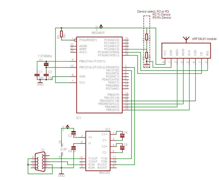
This is the circuit that I used for testing and
where the code is adapted to.
The code is the same for the RX and TX
device, with R2 or R3 you choose witch
device it need to be.
Keep in mind that the nRF24L01 runs at 3.3V and
that the i/o is 5V tolerant.
The code
In the code
is enough help to understand it, but here is some additional help.
You must
use a chip with hardware spi, the software spi isnt working. We need the
control over the SS (CSN) line our self to get the nRF24L01 working properly.
The
nRF24L01 can work in different modes. In this sample we choose to use Enhanced
shockburst mode so we can demonstrate the benefits in comparing with regular
transmitters.
In this
sample we send a 5 bytes pload with auto ACK, 3x re-transmit, 2Mbps, 0dbm
output trough pipe0 on channel 40.
The code is
not optimised for speed so it will not reach the 2Mbps. For example, the Spi
bus of the nRF24L01 can run max 8Mbps and we are using now 2Mbps, thats
7372800 / 4 (Clock divided Spi Clockrate). Further there are some delays that
can be removed if your not using serial communication with a pc thats very
slow in comparison with the air speed. Please read Brennen his tutorials how to
calculate maximum air speed.
'------------------------------------------------------------------
' Nordic
nRF24L01 data link demo in Enhanced Shockburst mode
' By
Evert Dekker 2007 nRF24L01@Evertdekker dotje com
' Created with Bascom-Avr: 1.11.8.3
'------------------------------------------------------------------
$regfile = "M8def.dat"
$crystal = 7372800
$baud = 19200
$hwstack = 40
$swstack = 20
$framesize = 40
'=== Declare sub routines
Declare Sub R_register(byval Command As Byte , Byval C_bytes As Byte)
Declare Sub W_register(byval C_bytes As Byte)
'=== Constante ===
'Define nRF24L01 interrupt flag's
Const Idle_int = &H00 'Idle, no interrupt pending
Const Max_rt = &H10 'Max #of Tx Retrans Interrupt
Const Tx_ds = &H20 'Tx Data Sent Interrupt
Const Rx_dr = &H40 'Rx Data Received
'SPI(nRF24L01) commands
Const Read_reg = &H00 'Define Read Command To Register
Const Write_reg = &H20 'Define Write Command To Register
Const Rd_rx_pload = &H61 'Define Rx Payload Register Address
Const Wr_tx_pload = &HA0 'Define Tx Payload Register Address
Const Flush_tx = &HE1 'Define Flush Tx Register Command
Const Flush_rx = &HE2 'Define Flush Rx Register Command
Const Reuse_tx_pl = &HE3 'Define Reuse Tx Payload Register Command
Const Nop_comm = &HFF 'Define No Operation , Might Be Used To
Read Status Register
'SPI(nRF24L01) registers(addresses)
Const Config_nrf = &H00 'Config' register address
Const En_aa = &H01 'Enable Auto Acknowledgment' register address
Const En_rxaddr = &H02 'Enabled RX addresses' register address
Const Setup_aw = &H03 'Setup address width' register address
Const Setup_retr = &H04 'Setup Auto. Retrans' register address
Const Rf_ch = &H05 'RF channel' register address
Const Rf_setup = &H06 'RF setup' register address
Const Status = &H07 'Status' register address
Const Observe_tx = &H08 'Observe TX' register address
Const Cd = &H09 'Carrier Detect' register address
Const Rx_addr_p0 = &H0A 'RX address pipe0' register address
Const Rx_addr_p1 = &H0B 'RX address pipe1' register address
Const Rx_addr_p2 = &H0C 'RX address pipe2' register address
Const Rx_addr_p3 = &H0D 'RX
address pipe3' register address
Const Rx_addr_p4 = &H0E 'RX address pipe4' register address
Const Rx_addr_p5 = &H0F 'RX address pipe5' register address
Const Tx_addr = &H10 'TX address' register address
Const Rx_pw_p0 = &H11 'RX payload width, pipe0' register address
Const Rx_pw_p1 = &H12 'RX payload width, pipe1' register address
Const Rx_pw_p2 = &H13 'RX payload width, pipe2' register address
Const Rx_pw_p3 = &H14 'RX payload width, pipe3' register address
Const Rx_pw_p4 = &H15 'RX payload width, pipe4' register address
Const Rx_pw_p5 = &H16 'RX payload width, pipe5' register address
Const Fifo_status = &H17 'FIFO Status Register' register address
'Various
Const True = 1
Const False = 0
'=== Config hardware ===
Config Spi = Hard , Interrupt = Off , Data
Order = Msb , Master = Yes , Polarity = Low , Phase = 0 , Clockrate =
4 , Noss = 1
'Software SPI is NOT working with the nRF24L01, use
hardware SPI only, but the SS pin must be controlled by our self
Config Pinc.5 = Output 'CE pin is output
Config Pinb.2 = Output 'SS pin is output
Config Pinc.4 = Input 'IRQ pin is input
Config Pinc.3 = Input 'TX/RX Device _select
Ce Alias Portc.5
Ss Alias Portb.2
Irq Alias Pinc.4
Txrx_device Alias Pinc.3
Spiinit 'init
the spi pins
Set Ce
Waitms 10 'Wait a moment until all hardware is
stable
Reset Ce 'Set CE pin low
Reset Ss 'Set
SS pin low (CSN pin)
Dim D_bytes(33) As Byte , B_bytes(33) As Byte 'Dim
the bytes use for SPI, D_bytes = outgoing B_bytes = Incoming
Dim Temp As Byte , W As Word
Dim Packet_count As Byte
If Txrx_device = True Then Goto
Main_tx 'Is this the RX or TX device?
'===Main
rx==========================================================================================================================
Main_rx:
Call R_register(status , 1) 'Read
STATUS register
Print "Rx_device" 'Send to terminal who i'm
Reset Ce 'Set CE low to access the registers
Gosub Setup_rx 'Setup
the nRF24L01 for RX
Waitms 2 'Add a delay before going in RX
Set Ce 'Set nRF20L01 in RX mode
Do 'Main loop for RX
If Irq = 0 Then 'Wait until IRQ occurs, pin becomes low on interrupt
Reset Ce 'Receiver must be disabled before reading
pload
Do 'Loop until all 3 fifo buffers are empty
Call R_register(rd_rx_pload
, 5) 'Read
5 bytes RX pload register
Print "Pload : " ; Hex(b_bytes(1)) ; Hex(b_bytes(2)) ; Hex(b_bytes(3)) ; Hex(b_bytes(4)) ; Hex(b_bytes(5)) 'Print the pload
Call R_register(fifo_status
, 1) 'Read
FIFO_STATUS
Loop Until
B_bytes(1).0 = True 'Test or RX_EMPTY bit is true, RX FIFO empty
D_bytes(1) = Write_reg + Status 'Reset the RX_DR status bit
D_bytes(2) = &B01000000 'Write 1 to RX_DR bit to reset IRQ
Call W_register(2)
Set Ce 'Enable receiver again
Waitms 2
End If
'Gosub Dump_registers 'Unremark me for debugging
Loop
Return
'===Main
tx==========================================================================================================================
Main_tx:
Print "TX_device" 'Send to terminal who i'm
D_bytes(1) = Flush_tx 'Flush the TX_fifo buffer
Call W_register(1)
D_bytes(1) = Write_reg +
Status 'Reset the IRQ bits
D_bytes(2) = &B00110000
Call W_register(2)
Do 'Main loop for TX
Incr Packet_count 'Increase the send packet counter, for test only
If Packet_count > 254 Then Packet_count =
0
Gosub Setup_tx 'Setup the nrf240l01 for TX
D_bytes(1) = Wr_tx_pload 'Put 5 bytes in the TX pload buffer
D_bytes(2) = &HAA 'Byte 1
D_bytes(3) = &HBB 'Byte 2
D_bytes(4) = &HCC 'Byte 3
D_bytes(5) = &H11 'Byte
4
D_bytes(6) = Packet_count 'Byte 5 will be increase every loop
Call W_register(6) 'Write 6 bytes to register
Waitms 2
Set Ce 'Set
CE for a short moment to transmit the fifo buffer
Waitms 1 '
Reset Ce '
Waitms 100 'Some delay to
read the output on the terminal, line can be removed for max. speed
W = 0 'Counter for time out
Do
If Irq = 0 Then
Call R_register(status
, 1)
Temp = B_bytes(1) And &B01110000 'Mask
the IRQ bits out the status byte
Select Case
Temp 'Which IRQ occurs
Case Max_rt 'MAX_RT
Print "Maximum number of TX retries,
Flussing the TX buffer now !"
D_bytes(1) = Flush_tx 'Flush the TX buffer
Call W_register(1)
D_bytes(1) = Write_reg + Status
D_bytes(2) = &B00010000 'Clear the MAX_RT IRQ bit
Call W_register(2)
Exit Do
Case Tx_ds 'TX_DS
Print "Packet " ; Packet_count ; " send and ACK received."
D_bytes(1) = Write_reg + Status
D_bytes(2) = &B00100000 'Clear the TX_DS IRQ bit
Call W_register(2)
Exit Do
Case Else 'Other IRQ ??
Print "Other irq " ; Bin(temp)
D_bytes(1) = Flush_tx 'Flush the TX buffer
Call W_register(1)
D_bytes(1) = Write_reg + Status
D_bytes(2) = &B00110000 'Clear both MAX_RT, TX_DS bits
Call W_register(2)
End Select
End If
Waitms 1 'Time out waiting for IRQ 1ms * 100
Incr W 'Increment W
If W >
100 Then 'Waited
for 100ms
Print "No irq response from RF20L01 within
100ms"
Exit Do 'Exit the wait loop
End If
Loop
Loop
Return
'=== Sub routines ===
Sub W_register(byval
C_bytes As Byte) 'Write
register with SPI
Reset Ss 'Manual control SS pin, set SS low before
shifting out the bytes
Spiout D_bytes(1) , C_bytes 'Shiftout the data bytes trough SPI ,
C_bytes is the amount bytes to be written
Set Ss 'Set SS high
End Sub
Sub R_register(byval
Command As Byte , Byval
C_bytes As Byte) As Byte 'C_bytes
= Count_bytes, number off bytes to be read
Reset Ss 'Manual controle SS pin, set low before
shifting in/out the bytes
Spiout Command ,
1 'First shiftout the register to be read
Spiin B_bytes(1) , C_bytes 'Read back the bytes from SPI sended by
nRF20L01
Set Ss 'Set SS back to high level
End Sub
Setup_rx: 'Setup for RX
D_bytes(1) = Write_reg +
Rx_addr_p0 'RX adress for pipe0
D_bytes(2) = &H34
D_bytes(3) = &H43
D_bytes(4) = &H10
D_bytes(5) = &H10
D_bytes(6) = &H01
Call W_register(6) 'Send 6 bytes to SPI
D_bytes(1) = Write_reg +
En_aa 'Enable auto ACK for pipe0
D_bytes(2) = &H01
Call W_register(2)
D_bytes(1) = Write_reg +
En_rxaddr 'Enable RX adress for pipe0
D_bytes(2) = &H01
Call W_register(2)
D_bytes(1) = Write_reg +
Rf_ch 'Set RF channel
D_bytes(2) = 40
Call W_register(2)
D_bytes(1) = Write_reg +
Rx_pw_p0 'Set RX pload width for pipe0
D_bytes(2) = 5
Call W_register(2)
D_bytes(1) = Write_reg +
Rf_setup 'Setup RF-> Output power 0dbm, datarate 2Mbps and LNA gain on
D_bytes(2) = &H0F
Call W_register(2)
D_bytes(1) = Write_reg +
Config_nrf 'Setup CONFIG-> PRX=1(RX_device), PWR_UP=1, CRC 2bytes, Enable CRC
D_bytes(2) = &H0F
Call W_register(2)
Return
Setup_tx: 'Setup for TX
D_bytes(1) = Write_reg +
Tx_addr 'TX adress
D_bytes(2) = &H34
D_bytes(3) = &H43
D_bytes(4) = &H10
D_bytes(5) = &H10
D_bytes(6) = &H01
Call W_register(6)
D_bytes(1) = Write_reg +
Rx_addr_p0 'RX adress for pipe0
D_bytes(2) = &H34
D_bytes(3) = &H43
D_bytes(4) = &H10
D_bytes(5) = &H10
D_bytes(6) = &H01
Call W_register(6)
D_bytes(1) = Write_reg +
En_aa 'Enable auto ACK for pipe0
D_bytes(2) = &H01
Call W_register(2)
D_bytes(1) = Write_reg +
En_rxaddr 'Enable RX adress for pipe0
D_bytes(2) = &H01
Call W_register(2)
D_bytes(1) = Write_reg +
Rf_ch 'Set RF channel
D_bytes(2) = 40
Call W_register(2)
D_bytes(1) = Write_reg +
Rf_setup 'Setup RF-> Output power 0dbm, datarate 2Mbps and LNA gain on
D_bytes(2) = &H0F
Call W_register(2)
D_bytes(1) = Write_reg +
Config_nrf 'Setup CONFIG-> PRX=0(TX_device), PWR_UP=1, CRC 2bytes, Enable CRC
D_bytes(2) = &H0E
Call W_register(2)
Return
Dump_registers: 'Dumps all nRF24L01 registers to the terminal, handy for debugging
Print "* Dump nRF24L01 Registers *"
Call R_register(config_nrf , 1)
Print "CONFIG : " ; Bin(b_bytes(1))
Call R_register(en_aa , 1)
Print "EN_AA : " ; Bin(b_bytes(1))
Call R_register(en_rxaddr , 1)
Print "EN_RXADDR : " ; Bin(b_bytes(1))
Call R_register(setup_aw , 1)
Print "SETUP_AW : " ; Bin(b_bytes(1))
Call R_register(setup_retr , 1)
Print "SETUP_RETR : " ; Bin(b_bytes(1))
Call R_register(rf_ch , 1)
Print "RF_CH : " ; B_bytes(1)
Call R_register(rf_setup , 1)
Print "RF_SETUP : " ; Bin(b_bytes(1))
Call R_register(status , 1)
Print "STATUS : " ; Bin(b_bytes(1))
Call R_register(observe_tx , 1)
Print "OBSERVE_TX : " ; Bin(b_bytes(1))
Call R_register(cd , 1)
Print "CD : " ; Bin(b_bytes(1))
Call R_register(rx_addr_p0 , 5)
Print "RX_ADDR_P0 : " ; Hex(b_bytes(1)) ; Hex(b_bytes(2)) ; Hex(b_bytes(3)) ; Hex(b_bytes(4)) ; Hex(b_bytes(5))
Call R_register(rx_addr_p1 , 5)
Print "RX_ADDR_P1 : " ; Hex(b_bytes(1)) ; Hex(b_bytes(2)) ; Hex(b_bytes(3)) ; Hex(b_bytes(4)) ; Hex(b_bytes(5))
Call R_register(rx_addr_p2 , 5)
Print "RX_ADDR_P2 : " ; Hex(b_bytes(1)) ; Hex(b_bytes(2)) ; Hex(b_bytes(3)) ; Hex(b_bytes(4)) ; Hex(b_bytes(5))
Call R_register(rx_addr_p3 , 5)
Print "RX_ADDR_P3 : " ; Hex(b_bytes(1)) ; Hex(b_bytes(2)) ; Hex(b_bytes(3)) ; Hex(b_bytes(4)) ; Hex(b_bytes(5))
Call R_register(rx_addr_p4 , 5)
Print "RX_ADDR_P4 : " ; Hex(b_bytes(1)) ; Hex(b_bytes(2)) ; Hex(b_bytes(3)) ; Hex(b_bytes(4)) ; Hex(b_bytes(5))
Call R_register(rx_addr_p5 , 5)
Print "RX_ADDR_P5 : " ; Hex(b_bytes(1)) ; Hex(b_bytes(2)) ; Hex(b_bytes(3)) ; Hex(b_bytes(4)) ; Hex(b_bytes(5))
Call R_register(tx_addr , 5)
Print "TX_ADDR : " ; Hex(b_bytes(1)) ; Hex(b_bytes(2)) ; Hex(b_bytes(3)) ; Hex(b_bytes(4)) ; Hex(b_bytes(5))
Call R_register(rx_pw_p0 , 5)
Print "RX_PW_P0 : " ; Hex(b_bytes(1)) ; Hex(b_bytes(2)) ; Hex(b_bytes(3)) ; Hex(b_bytes(4)) ; Hex(b_bytes(5))
Call R_register(rx_pw_p1 , 5)
Print "RX_PW_P1 : " ; Hex(b_bytes(1)) ; Hex(b_bytes(2)) ; Hex(b_bytes(3)) ; Hex(b_bytes(4)) ; Hex(b_bytes(5))
Call R_register(rx_pw_p2 , 5)
Print "RX_PW_P2 : " ; Hex(b_bytes(1)) ; Hex(b_bytes(2)) ; Hex(b_bytes(3)) ; Hex(b_bytes(4)) ; Hex(b_bytes(5))
Call R_register(rx_pw_p3 , 5)
Print "RX_PW_P3 : " ; Hex(b_bytes(1)) ; Hex(b_bytes(2)) ; Hex(b_bytes(3)) ; Hex(b_bytes(4)) ; Hex(b_bytes(5))
Call R_register(rx_pw_p4 , 5)
Print "RX_PW_P4 : " ; Hex(b_bytes(1)) ; Hex(b_bytes(2)) ; Hex(b_bytes(3)) ; Hex(b_bytes(4)) ; Hex(b_bytes(5))
Call R_register(rx_pw_p5 , 5)
Print "RX_PW_P5 : " ; Hex(b_bytes(1)) ; Hex(b_bytes(2)) ; Hex(b_bytes(3)) ; Hex(b_bytes(4)) ; Hex(b_bytes(5))
Call R_register(fifo_status , 1)
Print "FIFO_STATUS : " ; Bin(b_bytes(1))
Return
Updated code for using with Xmega32a4: 'in this sample you can send 2 byte numbrical and learn how send more byte of different data
'------------------------------------------------------------------
' Nordic nRF24L01 data link demo in Enhanced Shockburst mode
' By shobeir 2012 shobeir90@yahoo.co.uk
' Created with Bascom-Avr: 2.0.7.3
'------------------------------------------------------------------
'$regfile = "M8def.dat"
$regfile = "xm32a4def.dat"
'$crystal = 7372800
$crystal = 32000000
'$baud = 19200
$hwstack = 255
$swstack = 255
$framesize = 255
$lib "xmega.lib"
$external _xmegafix_clear
$external _xmegafix_rol_r1014
Config Osc = Enabled , 32mhzosc = Enabled 'We use internal 32MHz
Config Sysclock = 32mhz , Prescalea = 1 , Prescalebc = 1_1 'Internal 32MHz, no prescaler
Config Priority = Static , Vector = Application , Lo = Enabled
'=== Declare sub routines
Declare Sub R_register(byval Command As Byte , Byval C_bytes As Byte)
Declare Sub W_register(byval C_bytes As Byte)
'=== Constante ===
'Define nRF24L01 interrupt flag's
Const Idle_int = &H00 'Idle, no interrupt pending
Const Max_rt = &H10 'Max #of Tx Retrans Interrupt
Const Tx_ds = &H20 'Tx Data Sent Interrupt
Const Rx_dr = &H40 'Rx Data Received
'SPI(nRF24L01) commands
Const Read_reg = &H00 'Define Read Command To Register
Const Write_reg = &H20 'Define Write Command To Register
Const Rd_rx_pload = &H61 'Define Rx Payload Register Address
Const Wr_tx_pload = &HA0 'Define Tx Payload Register Address
Const Flush_tx = &HE1 'Define Flush Tx Register Command
Const Flush_rx = &HE2 'Define Flush Rx Register Command
Const Reuse_tx_pl = &HE3 'Define Reuse Tx Payload Register Command
Const Nop_comm = &HFF 'Define No Operation , Might Be Used To Read Status Register
'SPI(nRF24L01) registers(addresses)
Const Config_nrf = &H00 'Config' register address
Const En_aa = &H01 'Enable Auto Acknowledgment' register address
Const En_rxaddr = &H02 'Enabled RX addresses' register address
Const Setup_aw = &H03 'Setup address width' register address
Const Setup_retr = &H04 'Setup Auto. Retrans' register address
Const Rf_ch = &H05 'RF channel' register address
Const Rf_setup = &H06 'RF setup' register address
Const Status = &H07 'Status' register address
Const Observe_tx = &H08 'Observe TX' register address
Const Cd = &H09 'Carrier Detect' register address
Const Rx_addr_p0 = &H0A 'RX address pipe0' register address
Const Rx_addr_p1 = &H0B 'RX address pipe1' register address
Const Rx_addr_p2 = &H0C 'RX address pipe2' register address
Const Rx_addr_p3 = &H0D 'RX address pipe3' register address
Const Rx_addr_p4 = &H0E 'RX address pipe4' register address
Const Rx_addr_p5 = &H0F 'RX address pipe5' register address
Const Tx_addr = &H10 'TX address' register address
Const Rx_pw_p0 = &H11 'RX payload width, pipe0' register address
Const Rx_pw_p1 = &H12 'RX payload width, pipe1' register address
Const Rx_pw_p2 = &H13 'RX payload width, pipe2' register address
Const Rx_pw_p3 = &H14 'RX payload width, pipe3' register address
Const Rx_pw_p4 = &H15 'RX payload width, pipe4' register address
Const Rx_pw_p5 = &H16 'RX payload width, pipe5' register address
Const Fifo_status = &H17 'FIFO Status Register' register address
'Various
Const True = 1
Const False = 0
'=== Config hardware ===
'Config Spi = Hard , Interrupt = Off , Data Order = Msb , Master = Yes , Polarity = Low , Phase = 0 , Clockrate = 4 , Noss = 1
'Config Spic = Hard , Master = Yes , Mode = 0 , Clockdiv = Clk16 , Data_order = Msb , Ss = Auto
'Software SPI is NOT working with the nRF24L01, use hardware SPI only, but the SS pin must be controlled by our self
Config Pinb.0 = Output 'test pin
Config Pinc.1 = Output 'CE pin is output
Config Pinc.4 = Output 'SS pin is output
Config Portc.5 = Output
Config Portc.7 = Output
Set Pinc.4
Config Pinc.0 = Input 'IRQ pin is input
Config Pinc.3 = Input 'TX/RX Device _select
Ddrc = &B1011_1010
Ce Alias Portc.1
Ss Alias Portc.4
Irq Alias Pinc.0
Txrx_device Alias Pinc.3
Config Spi = Soft , Din = Pinc.6 , Dout = Portc.5 , Ss = None , Clock = Portc.7 , Spiin = 0 , Mode = 0
Spiinit 'init the spi pins
Set Ce
Waitms 10 'Wait a moment until all hardware is stable
Reset Ce 'Set CE pin low
Reset Ss 'Set SS pin low (CSN pin)
Dim D_bytes(33) As Byte , B_bytes(33) As Byte 'Dim the bytes use for SPI, D_bytes = outgoing B_bytes = Incoming
Dim Temp As Byte , W As Word
Dim Packet_count As Byte
Dim Lword As Word , L As Word
If Txrx_device = True Then Goto Main_tx 'Is this the RX or TX device?
'**********************test
'Do
'Portb.0 = Not Portb.0
'Waitms 300
'Loop
'===Main rx==========================================================================================================================
Main_rx:
Set Portb.0
Waitms 200
Reset Portb.0
Call R_register(status , 1) 'Read STATUS register
Print "Rx_device" 'Send to terminal who i'm
Reset Ce 'Set CE low to access the registers
Gosub Setup_rx 'Setup the nRF24L01 for RX
Waitms 2 'Add a delay before going in RX
Set Ce 'Set nRF20L01 in RX mode
Do 'Main loop for RX
'Portb.0 = 1
If Irq = 0 Then 'Wait until IRQ occurs, pin becomes low on interrupt
Reset Ce 'Receiver must be disabled before reading pload
Do 'Loop until all 3 fifo buffers are empty
Call R_register(rd_rx_pload , 5) 'Read 5 bytes RX pload register
Print "Pload : " ; Hex(b_bytes(1)) ; Hex(b_bytes(2)) ; Hex(b_bytes(3)) ; Hex(b_bytes(4)) ; Hex(b_bytes(5)) 'Print the pload
' Lword = &H100 * B_bytes(1)
' Lword = Lword Or B_bytes(2)
L = 0
L = B_bytes(2)
Swap L
Lword = B_bytes(1) + L
If Lword = 65535 Then 'Or B_bytes(2) = 12 Or B_bytes(3) = 12 Or B_bytes(4) = 12 Or B_bytes(5) = 12 Then
Portb.0 = Not Portb.0
Else
Reset Portb.0
End If
Call R_register(fifo_status , 1) 'Read FIFO_STATUS
Loop Until B_bytes(1).0 = True 'Test or RX_EMPTY bit is true, RX FIFO empty
D_bytes(1) = Write_reg + Status 'Reset the RX_DR status bit
D_bytes(2) = &B01000000 'Write 1 to RX_DR bit to reset IRQ
Call W_register(2)
Set Ce 'Enable receiver again
Waitms 2
End If
'Gosub Dump_registers 'Unremark me for debugging
Loop
Return
'===Main tx==========================================================================================================================
Main_tx:
Print "TX_device" 'Send to terminal who i'm
D_bytes(1) = Flush_tx 'Flush the TX_fifo buffer
Call W_register(1)
D_bytes(1) = Write_reg + Status 'Reset the IRQ bits
D_bytes(2) = &B00110000
Call W_register(2)
Do 'Main loop for TX
Incr Packet_count 'Increase the send packet counter, for test only
If Packet_count > 254 Then Packet_count = 0
Gosub Setup_tx 'Setup the nrf240l01 for TX
D_bytes(1) = Wr_tx_pload 'Put 5 bytes in the TX pload buffer
D_bytes(2) = &HAA 'Byte 1
D_bytes(3) = &HBB 'Byte 2
D_bytes(4) = &HCC 'Byte 3
D_bytes(5) = &H11 'Byte 4
D_bytes(6) = Packet_count 'Byte 5 will be increase every loop
Call W_register(6) 'Write 6 bytes to register
Waitms 2
Set Ce 'Set CE for a short moment to transmit the fifo buffer
Waitms 1 '
Reset Ce '
'Waitms 100 'Some delay to read the output on the terminal, line can be removed for max. speed
Waitms 10
W = 0 'Counter for time out
Do
'test
Do
Lword = 65535
Portb.0 = Not Portb.0
Gosub Setup_tx
D_bytes(1) = Wr_tx_pload
D_bytes(2) = Lword And &H00FF
L = &HFF00 And Lword
Swap L
D_bytes(3) = L And &H00FF
Call W_register(6)
Waitms 2
Set Ce 'Set CE for a short moment to transmit the fifo buffer
Waitms 1 '
Reset Ce
Waitms 100
If Irq = 0 Then
Call R_register(status , 1)
D_bytes(1) = Flush_tx 'Flush the TX buffer
Call W_register(1)
D_bytes(1) = Write_reg + Status
D_bytes(2) = &B00110000 'Clear both MAX_RT, TX_DS bits
Call W_register(2)
End If
Loop
'tested
If Irq = 0 Then
Call R_register(status , 1)
Temp = B_bytes(1) And &B01110000 'Mask the IRQ bits out the status byte
Select Case Temp 'Which IRQ occurs
Case Max_rt 'MAX_RT
Print "Maximum number of TX retries, Flushing the TX buffer now !"
D_bytes(1) = Flush_tx 'Flush the TX buffer
Call W_register(1)
D_bytes(1) = Write_reg + Status
D_bytes(2) = &B00010000 'Clear the MAX_RT IRQ bit
Call W_register(2)
Exit Do
Case Tx_ds 'TX_DS
Print "Packet " ; Packet_count ; " send and ACK received."
' D_bytes(1) = 12
' Call W_register(1)
D_bytes(1) = Write_reg + Status
D_bytes(2) = &B00100000 'Clear the TX_DS IRQ bit
Call W_register(2)
Exit Do
Case Else 'Other IRQ ??
Print "Other irq " ; Bin(temp)
D_bytes(1) = Flush_tx 'Flush the TX buffer
Call W_register(1)
D_bytes(1) = Write_reg + Status
D_bytes(2) = &B00110000 'Clear both MAX_RT, TX_DS bits
Call W_register(2)
End Select
End If
Waitms 1 'Time out waiting for IRQ 1ms * 100
Incr W 'Increment W
If W > 100 Then 'Waited for 100ms
Print "No irq response from RF20L01 within 100ms"
Exit Do 'Exit the wait loop
End If
Loop
Loop
Return
'**********************************************************************************************w reg
'=== Sub routines ===
Sub W_register(byval C_bytes As Byte) 'Write register with SPI
Reset Ss 'Manual control SS pin, set SS low before shifting out the bytes
Spiout D_bytes(1) , C_bytes 'Shiftout the data bytes trough SPI , C_bytes is the amount bytes to be written
Set Ss 'Set SS high
End Sub
'**********************************************************************************************r reg
Sub R_register(byval Command As Byte , Byval C_bytes As Byte) As Byte 'C_bytes = Count_bytes, number off bytes to be read
Reset Ss 'Manual controle SS pin, set low before shifting in/out the bytes
Spiout Command , 1 'First shiftout the register to be read
Spiin B_bytes(1) , C_bytes 'Read back the bytes from SPI sended by nRF20L01
Set Ss 'Set SS back to high level
End Sub
Setup_rx: 'Setup for RX
D_bytes(1) = Write_reg + Rx_addr_p0 'RX adress for pipe0
D_bytes(2) = &H34
D_bytes(3) = &H43
D_bytes(4) = &H10
D_bytes(5) = &H10
D_bytes(6) = &H01
Call W_register(6) 'Send 6 bytes to SPI
D_bytes(1) = Write_reg + En_aa 'Enable auto ACK for pipe0
D_bytes(2) = &H01
Call W_register(2)
D_bytes(1) = Write_reg + En_rxaddr 'Enable RX adress for pipe0
D_bytes(2) = &H01
Call W_register(2)
D_bytes(1) = Write_reg + Rf_ch 'Set RF channel
D_bytes(2) = 40
Call W_register(2)
D_bytes(1) = Write_reg + Rx_pw_p0 'Set RX pload width for pipe0
D_bytes(2) = 5
Call W_register(2)
D_bytes(1) = Write_reg + Rf_setup 'Setup RF-> Output power 0dbm, datarate 2Mbps and LNA gain on
D_bytes(2) = &H0F
Call W_register(2)
D_bytes(1) = Write_reg + Config_nrf 'Setup CONFIG-> PRX=1(RX_device), PWR_UP=1, CRC 2bytes, Enable CRC
D_bytes(2) = &H0F
Call W_register(2)
Return
Setup_tx: 'Setup for TX
D_bytes(1) = Write_reg + Tx_addr 'TX adress
D_bytes(2) = &H34
D_bytes(3) = &H43
D_bytes(4) = &H10
D_bytes(5) = &H10
D_bytes(6) = &H01
Call W_register(6)
D_bytes(1) = Write_reg + Rx_addr_p0 'RX adress for pipe0
D_bytes(2) = &H34
D_bytes(3) = &H43
D_bytes(4) = &H10
D_bytes(5) = &H10
D_bytes(6) = &H01
Call W_register(6)
D_bytes(1) = Write_reg + En_aa 'Enable auto ACK for pipe0
D_bytes(2) = &H01
Call W_register(2)
D_bytes(1) = Write_reg + En_rxaddr 'Enable RX adress for pipe0
D_bytes(2) = &H01
Call W_register(2)
D_bytes(1) = Write_reg + Rf_ch 'Set RF channel
D_bytes(2) = 40
Call W_register(2)
D_bytes(1) = Write_reg + Rf_setup 'Setup RF-> Output power 0dbm, datarate 2Mbps and LNA gain on
D_bytes(2) = &H0F
Call W_register(2)
D_bytes(1) = Write_reg + Config_nrf 'Setup CONFIG-> PRX=0(TX_device), PWR_UP=1, CRC 2bytes, Enable CRC
D_bytes(2) = &H0E
Call W_register(2)
Return
Dump_registers: 'Dumps all nRF24L01 registers to the terminal, handy for debugging
Print "* Dump nRF24L01 Registers *"
Call R_register(config_nrf , 1)
Print "CONFIG : " ; Bin(b_bytes(1))
Call R_register(en_aa , 1)
Print "EN_AA : " ; Bin(b_bytes(1))
Call R_register(en_rxaddr , 1)
Print "EN_RXADDR : " ; Bin(b_bytes(1))
Call R_register(setup_aw , 1)
Print "SETUP_AW : " ; Bin(b_bytes(1))
Call R_register(setup_retr , 1)
Print "SETUP_RETR : " ; Bin(b_bytes(1))
Call R_register(rf_ch , 1)
Print "RF_CH : " ; B_bytes(1)
Call R_register(rf_setup , 1)
Print "RF_SETUP : " ; Bin(b_bytes(1))
Call R_register(status , 1)
Print "STATUS : " ; Bin(b_bytes(1))
Call R_register(observe_tx , 1)
Print "OBSERVE_TX : " ; Bin(b_bytes(1))
Call R_register(cd , 1)
Print "CD : " ; Bin(b_bytes(1))
Call R_register(rx_addr_p0 , 5)
Print "RX_ADDR_P0 : " ; Hex(b_bytes(1)) ; Hex(b_bytes(2)) ; Hex(b_bytes(3)) ; Hex(b_bytes(4)) ; Hex(b_bytes(5))
Call R_register(rx_addr_p1 , 5)
Print "RX_ADDR_P1 : " ; Hex(b_bytes(1)) ; Hex(b_bytes(2)) ; Hex(b_bytes(3)) ; Hex(b_bytes(4)) ; Hex(b_bytes(5))
Call R_register(rx_addr_p2 , 5)
Print "RX_ADDR_P2 : " ; Hex(b_bytes(1)) ; Hex(b_bytes(2)) ; Hex(b_bytes(3)) ; Hex(b_bytes(4)) ; Hex(b_bytes(5))
Call R_register(rx_addr_p3 , 5)
Print "RX_ADDR_P3 : " ; Hex(b_bytes(1)) ; Hex(b_bytes(2)) ; Hex(b_bytes(3)) ; Hex(b_bytes(4)) ; Hex(b_bytes(5))
Call R_register(rx_addr_p4 , 5)
Print "RX_ADDR_P4 : " ; Hex(b_bytes(1)) ; Hex(b_bytes(2)) ; Hex(b_bytes(3)) ; Hex(b_bytes(4)) ; Hex(b_bytes(5))
Call R_register(rx_addr_p5 , 5)
Print "RX_ADDR_P5 : " ; Hex(b_bytes(1)) ; Hex(b_bytes(2)) ; Hex(b_bytes(3)) ; Hex(b_bytes(4)) ; Hex(b_bytes(5))
Call R_register(tx_addr , 5)
Print "TX_ADDR : " ; Hex(b_bytes(1)) ; Hex(b_bytes(2)) ; Hex(b_bytes(3)) ; Hex(b_bytes(4)) ; Hex(b_bytes(5))
Call R_register(rx_pw_p0 , 5)
Print "RX_PW_P0 : " ; Hex(b_bytes(1)) ; Hex(b_bytes(2)) ; Hex(b_bytes(3)) ; Hex(b_bytes(4)) ; Hex(b_bytes(5))
Call R_register(rx_pw_p1 , 5)
Print "RX_PW_P1 : " ; Hex(b_bytes(1)) ; Hex(b_bytes(2)) ; Hex(b_bytes(3)) ; Hex(b_bytes(4)) ; Hex(b_bytes(5))
Call R_register(rx_pw_p2 , 5)
Print "RX_PW_P2 : " ; Hex(b_bytes(1)) ; Hex(b_bytes(2)) ; Hex(b_bytes(3)) ; Hex(b_bytes(4)) ; Hex(b_bytes(5))
Call R_register(rx_pw_p3 , 5)
Print "RX_PW_P3 : " ; Hex(b_bytes(1)) ; Hex(b_bytes(2)) ; Hex(b_bytes(3)) ; Hex(b_bytes(4)) ; Hex(b_bytes(5))
Call R_register(rx_pw_p4 , 5)
Print "RX_PW_P4 : " ; Hex(b_bytes(1)) ; Hex(b_bytes(2)) ; Hex(b_bytes(3)) ; Hex(b_bytes(4)) ; Hex(b_bytes(5))
Call R_register(rx_pw_p5 , 5)
Print "RX_PW_P5 : " ; Hex(b_bytes(1)) ; Hex(b_bytes(2)) ; Hex(b_bytes(3)) ; Hex(b_bytes(4)) ; Hex(b_bytes(5))
Call R_register(fifo_status , 1)
Print "FIFO_STATUS : " ; Bin(b_bytes(1))
Return |