|
Eka Puji Widiyanto ( ekapujiw2002 (at) yahoo (dot) com ) - www.ex4.hostiz.com
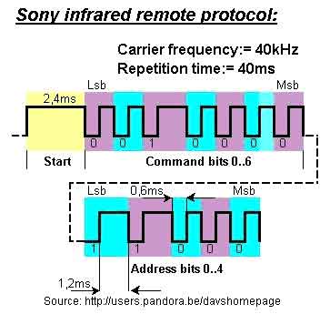
Sony remote control apply pulse width coding scheme for their protocol. The code exists of
12 bits sent on a 40kHz carrier wave. The code starts with a header of 2,4ms or
4 times T where T is 600µS. The header is followed by 7 command bits and 5
adres bits. The address and commands exists of logical ones and zeros. A
logical one is formed by a space of 600µS or 1T and a pulse of 1200 µS or 2T. A
logical zero is formed by a space of 600 µS and pulse of 600µS. The space
between 2 transmitted codes when a button is being pressed is 40mS The bits are
transmitted least significant bits first. The total length of a bitstream is
always 45ms. The detail of this protocol is depicted on the picture below (as
transmitted from the remote, at the receiver side, it is inverted):
How to decode that at the receiver?? This is my method :
- Configure an external interrupt at
the falling edge.
- If a falling edge found, start
Timer0 to count the time elapsed until a rising edge found.
- At the first time, always check
for a start bit based on its time length depicted above. If found than
set a flag for a sign for the next signal processing. If not found than
ignore the rest.
- If start bit found, then start to
count up every falling edge signal detected up to next 12bit. The shorter
length is denoted as zero (0) and the longer one is one (1), as depicted
above.
- After 12 bit data received, set a
flag indicate that the data is ready for reading and also reset the start
bit flag. This is my version. You can do other scheme of scenario.
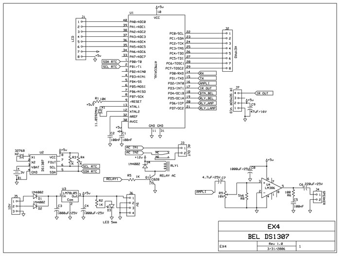
My schematic used ATMEGA16, but you can use other chips as
long it got interrupt pin. For the sensor I used vcd remote control sensor, but
you can use any type that have filter of 38KHz to 40KHz on it. On the schematic
you see DS1307 RTC, LCD connector, and also LM386 amplifier, thats the whole
project I build. But for this application note, I only focused on the Sony
decoding.
Source code below :
$regfile = "m16def.dat" 'the chip type, subtitutes with the one you like
$crystal = 11059200 'the crystal speed i used
Config Timer0 = Timer , Prescale = 256 'config timer0 for data trap timer
Stop Timer0 'stop timer0 first for other process
Config Pind.3 = Input 'configure the int pin , i used int1 pin
Set Portd.3 'set the pull up
resistor
Pin_ir Alias Pind.3 'alias for easy naming
Config Int1 = Falling 'configure int1 on falling edge
On Int1 Isr_int1 'the isr label
Dim Data_ir As Word 'the variabel need for the purpose
Dim Cnt_ir As Byte
Dim Flag_ir_start As Bit
Dim Flag_ir_ok As Bit
Print "SONY REMOTE DECODER" 'print some output to rx
Enable Interrupts 'enable global interrupt
Enable Int1 'enable int1 interrupt
Do 'main program start here
If Flag_ir_ok = 1 Then 'wait flag_ir_ok=1
Reset Flag_ir_ok 'reset the flag
Disable Int1 'disable the int1, so ignore all ir data from here
Print Data_ir 'print the data
Reset Flag_ir_ok 'reset the flag
Enable Int1 'enable the int1 interrupt to receive ir sony again
End If
Wait 1 'wait for sometime
Loop
'isr for infrared sensor
Isr_int1:
Timer0 = 0 'start timer0 to count
Start Timer0
Bitwait Pin_ir , Set 'wait the pin_ir to high again
Stop Timer0 'stop timer0
If Cnt_ir = 0 Then 'if this is the 1st data
If Timer0 > 111 And Timer0 < 114 Then 'check for
a start bit, with prescale=256 and
Set Flag_ir_start 'crystal 11,0592MHz, got timer0 value between 111 and 114
Incr Cnt_ir 'as the correct ir start bit. Measure all the neccessary bit first
End If ' if you want to change it
End If
If Flag_ir_start = 1 And Cnt_ir > 0 Then 'a start bit found -> start sampling for next 12 bit
Decr Cnt_ir
If Timer0 < 32 Then 'timer0<32 then it is a zero(0), else it is a one (1)
Data_ir.cnt_ir = 0 'assign it to a word value for easy recording
Else
Data_ir.cnt_ir = 1
End If
Cnt_ir = Cnt_ir + 2
If Cnt_ir > 11 Then 'got all 12 bit
Shift Data_ir , Right , 1 'get rid of the start bit
Reset Flag_ir_start 'reset the start bit flag
Set Flag_ir_ok 'the data is ready to be read
Cnt_ir = 0 'reset the counter
End If
End If
Return
|