by K.S.Sankar - Mostek Electronics ( www.mostek.biz )
Originaly published in ELECTRONICS FOR YOU magazine ( INDIA - W W W . E F Y M A G . C O M )
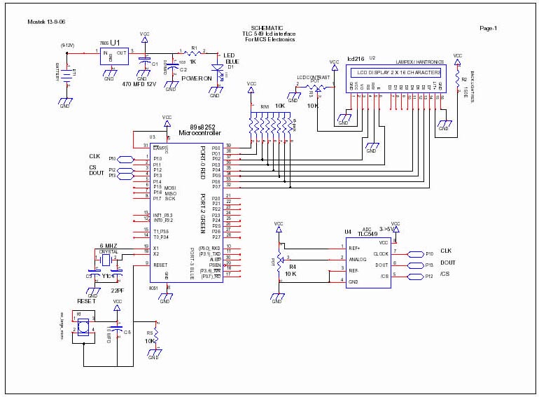
If you run out of Port pins when designing
with parallel interface 8-bit ADC
like the 0804, switch over to the
new serial interface 8-bit ADC chips
like the TLC549 from Texas Instruments .
This 8-pin ADC gives you 8-bit resolution with a 3 way interface saving you
precious port pins in projects using smaller micros like the 2051.
This article provides valuable info on
the SPI interface using CS DIN and CLOCK pulses. The micro controller used
is ATMEL-89s8252 running at 6Mhz for
convenience although the program will work on a smaller footprint micro.
LCD is used
to display the output 0-255 with an adjustable pot in the circuit that provides
0v to 5v to the analogue IN.
Brief Details about TLC549 form the data sheet:- 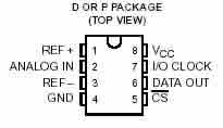
_ 8-Bit Resolution A/D
Converter
_ Differential Reference Input
Voltages
_ Conversion Time ...17 ms Max
_ Wide Supply Range ...3 V to 6
V
_ Low Power Consumption ...15
mW Max
_ CMOS Technology
Description
The TLC548 and TLC549 are CMOS analog-to-digital
converter (ADC) integrated circuits built around an 8-bit switched-capacitor
successive-approximation ADC. These devices are designed for serial interface
with a microprocessor or peripheral through a 3-state data output and an analog
input. The TLC548 and TLC549 use only the input/output clock (I/O CLOCK) input
along with the chip select (CS) input for data control. The maximum I/O CLOCK
input frequency of the TLC548 is 2.048 MHz, and the I/O CLOCK input frequency
of the TLC549 is specified up to 1.1 MHz.
More info in the data sheet
The simple
source code is given below:-
' 549lcd.bas
' research on TLC549 adc ic 8-bit 3 wire interface
' by K.S.Sankar www.mostek.biz for MCS Electronics AN
' 3-oct-2006
' LCD SHOULD DISPLAY 0-255 FOR 0V TO 5 VOLT INPUT
$crystal
= 6000000
$regfile
= "89s8252.dat"
Config Lcd = 16 * 2
Config
Lcdpin = Pin , Db4 = P0.4 , Db5 = P0.5 , Db6 = P0.6 , Db7 = P0.7
Config
Lcdpin = Pin , E = P0.3 , Rs = P0.2
P0 = 0
P1 = 0
P2 = 0
P3 = 0
Declare Sub
Getval_549(w1 As Byte)
Dim W1 As Byte
Cs Alias P1.2
Clock Alias P1.0
Din Alias P1.1
' not used
Dout Alias P1.3
Dout = 1
' INPUT PULLED HIGH FOR READING
Dim V As Byte
Dim
Bit2 As Bit
Cls
Lcd "ADC 549 RESEARCH"
Begin:
Call
Getval_549(v)
' ans in v
Lowerline
Lcd " "
Lowerline
Lcd "Ans=" ; V
Waitms
255
Goto
Begin
' SUBROUTINES / FUNCTIONS
'=-=-=-=-=-=-=-=-=-=-=-=-=
Sub
Getval_549(_w As Byte)
Dim _w As Byte , _j As Byte
Cs = 0
V = 0
For _j = 1 To 8
' read dout pin
Bit2 = Dout
Shift V , Left , 1
V.0 = Bit2
' send clock PULSE
Clock = 1
Clock = 0
Next _j
Cs = 1
Waitms 1
_w = V
End Sub
End
|