by K.S.Sankar - Mostek Electronics ( www.mostek.biz )
Originaly published in ELECTRONICS FOR YOU magazine ( INDIA - W W W . E F Y M A G . C O M )
Countdown timers can be constructed using digital Ics,
up/down counters and 555 timers . These
circuits require too many Ics.
Here is a simple design based on ATMEL 89c2051 a 20-pin micro controller that does the countdown
timing for a period of 99 minutes with two 7-segment displays showing the
actual time left. During the timing period a relay output is latched and a
flashing led indicates timing in progress.
Four switches are used to START / STOP and to set UP/DOWN
the timer.
The timing can also be changed while the counting is in
progress. Auto repeat key logic also works if you hold the UP or DOWN key
continuously, the timing changes at a faster rate. Click here to download source code and article PDF
The source program
in BASCOM-51 is listed below:
'--------------------------------------------------------------
' efycd99m.bas 99 min countdown relay timer
' for EFY Magazine
' language used: BASCOM-51 from www.mcselec.com
' Micro controller used= Atmel 89c2051
' by K.S.Sankar www.mostek.biz
' 16-1-2006 for pcb code b27b
'--------------------------------------------------------------
' define crystal speed
$crystal = 6000000
$regfile = "89c2051.dat"
' define variables
Dim I As Byte
Dim Sec_count As Byte
Dim Min_count As Byte
Dim Clock_word As Word
Dim Setmode As Bit
' declare function used
Declare Sub Fn7seg(_i As Byte)
Dim _i As Byte
'=-=-=-=-=-=-=-=-=-=
' declare interrupt routines
On Int0 Int0_int
On Int1 Int1_int
Enable Interrupts
Enable Int0
Enable Int1
'enable the interrupts
'=-=-=-=-=-=-=-=-=-=
' define alias names for start / stop switches
Sw_start Alias P3.0
Sw_stop Alias P3.1
' up /down switches are connected to int0 and int1
' Switch_up P3.2 (
int0)
' Switch_down P3.3 ( int1)
Relay_out Alias P3.7
Led_out Alias P3.4
' make ports 0
P1 = 0
P3 = &B00111111
' p1 port to ic4511 bcd -> 7 seg convertor ( 2
displays)
' p3 as input and output port
' configure timer0
Config Timer0 = Timer , Gate = Internal , Mode = 2
'Mode = 2 8 bit
auto reload
' set t0 internal interrupt 2000 times a sec
On Timer0 Timer_0_overflow_int
Load Timer0 , 250
Priority Set Timer0
Enable Interrupts
Enable Timer0
' dont start timer0 here
Begin:
' wait for sw-start press
' or interupts up/down to take place
Setmode = 0
Relay_out = 0
Led_out = 0
Sec_count = 0
Min_count = 0
I = 0
'=-=-=-=-=-=-=-=
Begin1:
Call Fn7seg(i)
If Sw_start = 0 Then
Goto Begin2
End If
If Sw_stop = 0 Then
While Sw_stop = 0
Wend
Relay_out = 0
Sec_count = 0
Goto Begin
End If
Goto Begin1
Begin2:
' relay on
Setmode = 0
Relay_out = 1
Start Timer0
Begin3:
I = 99 - Min_count
Call Fn7seg(i)
If I = 0 Then
Goto Over
End If
If Sw_start = 0 Then
Start Timer0
Setmode = 0
End If
If Sw_stop = 0 Then
Goto Over
End If
Goto Begin3
Over:
Stop Timer0
Relay_out = 0
Goto Begin
'end of main program
'=-=-=-=-=-= function below---- - -- -
Sub Fn7seg(_i As Byte)
Dim _ans As Byte
' display on two 7 seg
_ans = Makebcd(_i)
P1 = _ans
If Setmode = 1 Then
' if in set mode make display flicker
P1 = 255
' blankout the display
Waitms 30
' turn it on again
P1 = _ans
Waitms 30
End If
End Sub
' interrupt subroutine -----------------
Timer_0_overflow_int:
' program comes here 2000 times a sec with a 6mhz xtal
Incr Clock_word
If Clock_word > 2000 Then
Clock_word = 0
Incr Sec_count
' A Flashing Led When Timing Is In Progress
' 1 sec on and 1 sec off
Led_out = Led_out Xor 1
End If
If Sec_count = 60 Then
Sec_count = 0
Incr Min_count
End If
Return
'=-=-=-=-=-=-=-=-=-=-=-=-=-=-=-=-=-=-
Rem The Interrupt Handler For The Int1 Interrupt
Int1_int:
'DOWN
Stop Timer0
Setmode = 1
Incr Min_count
If Min_count >= 99 Then Min_count = 98
I = 99 - Min_count
Call Fn7seg(i)
Waitms 100
Return
'=-=-=-=-=-=-=-=-=-=-=-=-=-=-=-=-=-=-
Rem The Interrupt Handler For The Int0 Interrupt
Int0_int:
' UP
Stop Timer0
Setmode = 1
Decr Min_count
If Min_count = 255 Then Min_count = 0
If Min_count = 0 Then Min_count = 0
I = 99 - Min_count
Call Fn7seg(i)
Waitms 100
Return
End
' this program when compiled creates a binary file
' of just 802 bytes with only 8 variables defined in
' the program
' if such a user friendly language can create compact code
' I wonder why people still struggle to write in op codes
or
' languages full of semi-collons.....
' that is left to the reader to c
' end of program -=-=-=-=-=-=- written in bascom-51
' =-=-=-=-=-=-=-=
The program in hex is only 802 bytes and the 2051 micro can take upto 2k of code
This program can be modified to suits users requirement.
The hex file should be burnt into the chip using any
universal programmer suitable for Atmel 89c2051.
Circuit diagram below: 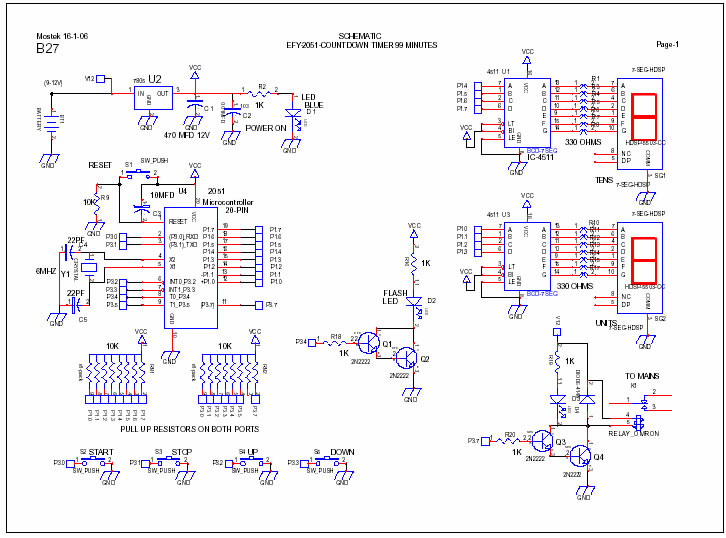
Circuit Explanation
The micro controller used is ATMEL
AT89c2051 a 20pin device with 2k of program memory.
Port-1 is used to drive two seven segment displays through
ic 4511 bcd to 7-segment converters. A crystal of 6Mhz is used. Timer0 is used as an internal COUNTER and increments a variable every
second and minute. This is used in the project for accurate timing.
The software wait for the start switch to start timing and
can be stopped anytime by pressing the stop switch. Up/Down set switches are directly handled by interrupt 0 and
1 in the software.
The 4 input switches are connected to port-3.
Port-3 does not have the bit p3.6 and it is ignored.
A flashing LED is connected to port 3.4 to show that timing
is in progress.
The relay ON pin is also connected to a transistor to switch
ON a 12v Relay which can activate any electrical device. The project can be
converted to 99 seconds timer by making
suitable changes in the source code.
The software is written using BASCOM-51. The source code is
self explanatory
K.S.Sankar
|


