|
|
| |
|
|
| |
|
AN #138 - RPM meter and rotational speed sensor KMI15/1 with AT90S2313 |

|
RPM meter and rotational speed sensor KMI15/1 with AT90S2313
In this AN I want provide step-by-step guide how to make project in BASCOM-AVR with all required things around to succesfull finish.
This AN show how to adapt or remake old analog RPM gauge in car to another sensor (engine :) ) or so with some theory about.
First some technical info about used sensor and schematics :
Sensor KMI15/1
The
KMI15/1 sensor detects rotational speed of ferrous gear wheels and
reference marks.The sensor consists of a magnetoresistive sensor
element, a signal conditioning integrated circuit in bipolar technology
and a magnetized ferrite magnet. The frequency of the digital current
output signal is proportional to the rotational speed of a gear wheel.
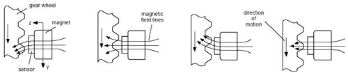
Functional principle
|
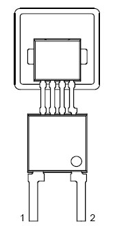 |
| 1 : VCC (typ. 12V)
2 : V- (output)
|
Sensor have only two pins, one for power supply and second for current
output. Output is current and have two states, 7mA for logic 0 and 14mA
for logic 1. Power supply is typicaly 12V (used in cars). Working
frequency are up to 25.000Hz.
For using with MCU this output must be converted to classic TTL logic. Conversion provide circuit below.
I1 is current source 7/14mA and is used only for testing, in real
operation I1 is replaced with sensor output. R1/C1 convert current to
voltage : 7mA = 0.7V and 14mA = 1.4V.
TLC 339 (LM339) is classic voltage comparator what compare input
voltage 0.7V/1.4V and make on output of comparator 0 or 5V.
Comparator is set to switch voltage on input above cca. 1V to logic 1
and below 1V to logic 0.
Output of comparator goes to circuit with 555. This circuit works as
schmitt-trigger and is used to ,,clean,, pulses from comparator.
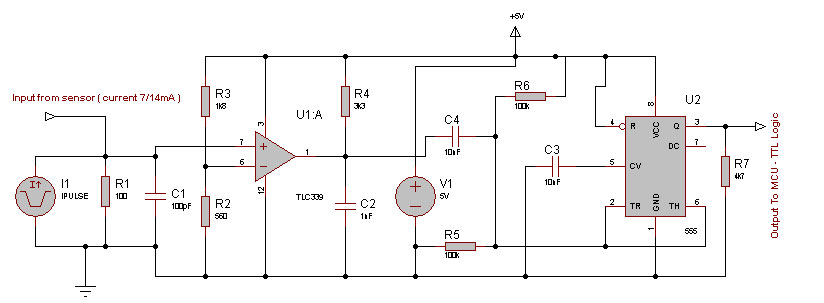
Schematic : convertor from current output of sensor (7/14mA) to TTL logic (0/5V)
| Parts list : | R1 - 100 ohm
R2 - 560 ohm
R3 - 1,8 K ohm
R4 - 3,3 K ohm
R5 - 100 K ohm
R6 - 100 K ohm
R7 - 4,7 K ohm | C1 - 100 pF
C2 - 1 nF
C3 - 10 nF
C4 - 10 nF
U1 - LM339
U2 - NE555
|
Schematic
with MCU is simple and I think not need any comments. RS232 line is
used only to debug/setup program but in testing I recommend it.
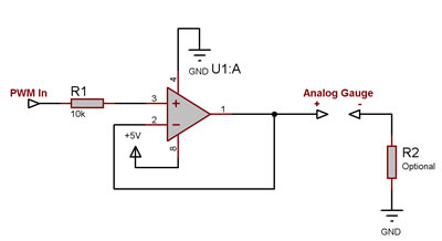
Note : PWM output
from MCU cannot be used to drive any gauges directly ! Between PWM out
and your gauge you must use amplifier to get more current and convert
impedance. I use NE5532 but can be used any of simple OPAMP like LM138
or so connected as ,,voltage follower,,. (schematic above)
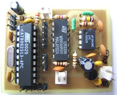 Finished electronics (without follower, follower is placed directly in gauge)
Program for MCU can be divide to some stages :
- get information about pulses via PulseIN in BASCOM (Figure 1)
- convert PulseIN value to frequency (Hz)
- recalculate frequency value to PWM value (Figure 2)
Table
in Figure1 show various combination of XTAL and Genus value used in
PulseIN value. Genus value you can found in mcs.lib (search for :
[_PULSE_IN] ), you can see it here as : @genus(9) ;THIS FOR 10 US UNITS but approx. depends on XTAL.. Genus(9) is default value present in mcs.lib. If you want change it, simple rewrite it in .lib and compile .lib before compiling your program.
Figure 1 - Hz vs PulseIn value
| Hz |
4Mhz (genus 9) |
10 Mhz (genus
9) |
4MHz (genus 2) |
4Mhz (genus 1) |
4Mhz (genus 0) |
4Mhz (genus 20) |
| 10 |
5128 |
6172 |
11844 |
15489 |
20135
|
2796 |
| 50 |
1025 |
1242 |
2368 |
3097 |
4026 |
559 |
| 100 |
512 |
617 |
1184 |
1548 |
1954 |
279 |
| 150 |
341 |
414 |
789 |
1032 |
1342 |
186 |
| 200 |
256 |
310 |
592 |
774 |
1006 |
139 |
| 1000 |
51 |
61 |
118 |
154 |
195 |
27 |
| 1500 |
34 |
41 |
78 |
103 |
133 |
18 |
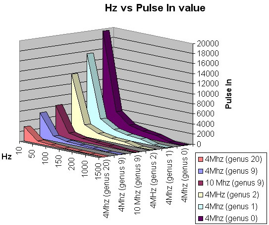 Best combination for my application I found with genus(0) and 4MHz XTAL
(10MHz maybe better but in test stage I not has any 10Mhz crystal free
:) )
Example of program is here, this program get pulse from PINB.2 and recalculate it to Hz.
Dim W As Word Dim Pinhz As Word Dim Temp As Single Dim Rpm As Word
Pinhz = 20135
Pulsein W , Pinb , 2 , 1
Temp = Pinhz / W
Temp = Temp * 10
Rpm = Temp / 16.5
Temp = Rpm * 60
When you look in line ,, Rpm = Temp / 16.5 ,, you
see constant 16.5, this constat show how many pulses you has for one
RPM and need to be changed to yours. Look at table below. Next important line is ,, Pinhz = 20135 ,, , it constatnt of PulseIN value at 10Hz (table up).
| RPM |
Hz (2
pulses/RPM) |
Hz
(2,5pulses/RPM) |
Hz big wheel
(16,5 pulses/RPM) |
| 100 |
3,33 |
4,2 |
27,5 |
| 800 |
26,67 |
33,3 |
220 |
| 1000 |
33,33 |
41,7 |
275 |
| 1500 |
50,00 |
62,5 |
412,5 |
| 2000 |
66,67 |
83,3 |
550 |
| 2500 |
83,33 |
104,2 |
687,5 |
| 3000 |
100,00 |
125,0 |
825 |
| 3500 |
116,67 |
145,8 |
962,5 |
| 4000 |
133,33 |
166,7 |
1100 |
| 4500 |
150,00 |
187,5 |
1237,5 |
| 5000 |
166,67 |
208,3 |
1375 |
| 5500 |
183,33 |
229,2 |
1512,5 |
This table show various RPM values with various numbers of pulses per revolution of motor. Frequency for your own sensor you can calculate simple : RPM * [pulses per 1 revolution] / 60 , in my case frequency for 100 RPM : 100 * 16,5 / 60 = 27,5 Hz for 100 RPM Here I want little explain how is measuring RPM in cars. ,,Normal
gas,, cars with 4 cylinders and classic ignition generate 4 pulses for
2 revolutions (pulses are taking from mechanical contacts from ignition
,,divider,,). This pulses usually has states ,,grounded,, and ,,free,,
because over this contacts is switching ignition coil (free state not must be really free because is switching inductive load !). In newest
cars is usually used other systems to geting RPM (sensor getting pulses
from flywheel between engine and gear), this must be discovered
yourself :) My car is 5 cylinder (AUDI 100) and is normal
situation I can get pulses from ignition and I can have 5pulses per 2
revolutions of motor - 2.5pulse/1 revolution. But I am not in normal situation :) My car is DIESEL and as you knows, DIESEL engines not has ignition :) What now ? :) Normaly
DIESEL engines with RPM gauge get pulses from alternator what has
special pin for RPM meter, but as I say I am not in normal situation :)
and I has bigger and more powerfull alternator from gas engine. Again, what next ? I
look over engine and only one reasonable place for getting pulses for
RPM meter is on engine head, on camshaft and his metal wheel what is
used to drive diesel-pump. This wheel has 33 tooths (ideal for this
type of sensor) and camshaft : engine has ratio 1:2 (this means ->
engine make 2 revolution and camshaft 1). From this with simple calculation I get 16.5 pulse for 1 engine revolution. Simple, not ? :)
This stage of AN can be simple adapt to any impulse source(sensor) and
recalculate RPM or get only Hz value, but calculating RPM to PWM is a
bit harder, ok, move to next figure.
As I say in previous, recalculate frequency to PWM value is not simple, but your Excel can help a lot.
For check parameters of original RPM gauge in car I use MCU (schemtic
from top + voltage follower) with test program and RS232 line. Simple
program in MCU get value for serial line and this value wrote to PWM
registers. Program may look like this :
Config Timer1 = Pwm , Prescale = 64 , Compare A Pwm = Clear Down , Pwm = 10
Dim A as word
Do
Input "PWM=" , A
Pwm1a = A
Loop
You can wrote random values in to terminal as you want until you found
value of PWM what is associated to specific RPM on gauge and wrote it
in to Excel table what can look as table below.
After, you can generate your graph with value what you measure. In my graph measured values are showed by red line
and you can see ,,linearity,, of your gauge or PWM. After this, use
Excel function named ,,Trend line,, what generate ,,ideal,, values
based on your data, this line is showed on graph by blue line.
Trend line function is nice because after generate ,,ideal,, value it
can show mathematic formula (in graph y = PWM value while x = RPM).
Program for calculate PWM from RPM look like this :
Dim Temp As Single
Dim Rpm As Word
Temp = 258.38 * Log(temp)
Temp = Temp - 1437.2
Rpm = Temp
Pwm1a = Rpm
Input value Temp has your actual RPM and on output, Temp has calculated PWM by math formula generated by Trend line.
Important line in program is ,,
RPM=Temp,, , RPM is Word while Temp is Single. This line make only
conversion from Single to Word because PWM register has problem with
Single values, without this line your program can work but some
calculated values is not acceptable for PWM register (some values
works, some not).
As you can see on graph , some calculated values are little
different as measured but error in calculation is very acceptable
because we use Analog gauge and error is not critical.
Figure 2 - RPM vs PWM
| RPM | PWM | Trend Line |
| 600 | 230 | 215,64 |
| 800 | 290 | 289,97 |
| 1000 | 330 | 347,63 |
| 1200 | 370 | 394,73 |
| 1400 | 420 | 434,56 |
| 1600 | 460 | 469,07 |
| 1800 | 490 | 499,50 |
| 2000 | 530 | 526,72 |
| 2200 | 550 | 551,35 |
| 2400 | 580 | 573,83 |
| 2600 | 610 | 594,51 |
| 2800 | 630 | 613,66 |
| 3000 | 660 | 631,49 |
| 3200 | 670 | 648,16 |
| 3400 | 685 | 663,82 |
| 3600 | 695 | 678,59 |
| 3800 | 705 | 692,56 |
| 4000 | 715 | 705,82 |
| 4200 | 720 | 718,42 |
| 4400 | 730 | 730,44 |
| 4600 | 735 | 741,93 |
| 4800 | 740 | 752,92 |
| 5000 | 750 | 763,47 |
| 5200 | 755 | 773,61 |
| 5400 | 765 | 783,36 |
| 5600 | 775 | 792,75 | | 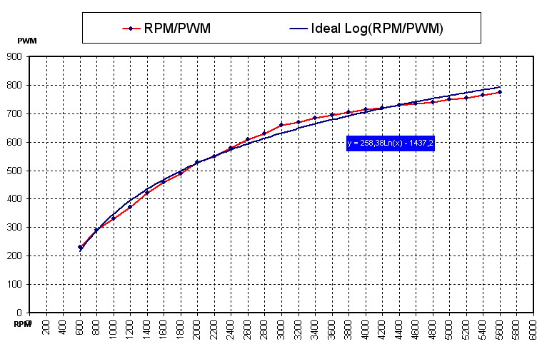
|
Complete program what I used in MCU (2313) is here (simple, no ? :) ) :
Note : this program calculate with recompiled mcs.lib with Genus(0) !
Config Timer1 = Pwm , Prescale = 64 , Compare A Pwm = Clear Down , Pwm = 10
Dim W As Word
Dim Pinhz As Word
Dim Temp As Single
Dim Rpm As Word
Pinhz = 20135
Pwm1a = 0
Do
Pulsein W , Pinb , 2 , 1
Temp = Pinhz / W
Temp = Temp * 10
Rpm = Temp / 16.5
Temp = Rpm * 60
Temp = 258.38 * Log(temp)
Temp = Temp - 1437.2
Rpm = Temp
Pwm1a = Rpm
Loop
Click to download source files
/Tomi - MCS Electronics
|
|
|
| |
|
|
|


