|
AN #209 - Driving a Single Digit LED Dot Matrix Display by Peter Preuß
1. Copyright : You can use
this App.-Note for free , if you use it for none profit applications .
The
Program Driving a Single Digit LED-Dot-Matrix Display.bas is part of this App.-Note.
2. Disclaimer : The author is not liable for any damages in
connection with this App-Note.
3. Electric savety : The
electronic of this application is supplied with 5VDC .
Make sure that you use CE certified power supply
to avoid an electric shock accident.
4. Motivation :
LED dot matrix display like the TA03-11 or
LTP-305 or TIL305 or MAN2 or ALS340A1.... ,
are still popular , because of the vintage
charm.
This mentioned displays are pin compatible.
To use this style of display it is
necessary to use a multiplex driving system in best case with
build-in
ASCII
Character Font.
But it is not easy to purchase for private
purpose integrated circuit with built-in
ASCII Character Font and Multiplexing the LED
Matrix.
Also such circuits are expensive for amateurs.
On the other hand you can find
modules with such display with a multiplex driver circuit , but this circuit
includes not a built-in ASCII Character Font . So you
need a library , so far I did not found a BASCOM-Lib.
So this situation was the reason to think
about how to use the dot matrix display like TA03-11SRT
and pin compatible type.
The
hard work was to build the pattern data for the characters of the Character
Font.
Characters are follow the data in accordance
to ASCII chart.
The result is to spend for each display an own
ATmega328P to build a addressable single digit module
with a
serial input RxD.
16
modules can be addressed by 4 address-pins.
5. Technical Information :
The module includes one
ATmega328P and a LED-Dot Matrix Display and 7 resistors 360 Ohm for R1..R7 .
The external module wiring is : GND ; +5V ; 4
termination for address ; RxD . Keep Reset / MOSI / MISO /
SCK for programming separate for each module.
16 modules are selectable by address .
All
modules can be paralleled at the RxD input / GND / +5V .
The
module receive a command : address and information for decimal point dp and
character.
Please
see the datasheet for ATmega328P and LED Dot Matrix Display.
Please
see the ASCII-Chart -> MSC BASCOM AVR Help Titel ASC.
Program
compares the command address and if the address fit to the hardware address , it
show's the new
character on the display.
The command start with @ , it means
"at" "address" "dp-on/off" "character"
"CR" .
Decimal
point is an extra column C1 and is handled separate .
The 5x7
Matrix is C2..C6 x R1..R7
The
Display is multiplexed at C2..C6 = Anodes times R1...R7 = Cathodes , incl.
C1=Dp.
For
R1..R7 is used PORTB , the information
is ; byte for C2 .... -> byte for C6
5 times
is PORTB multiplexed regarding C2...C6 ( PB0..PB6 is used for R1..R7 ; PB7 is
not used ) .
Columntime is the on-time for pixel , it can
be changed if necessary .
Delaytime is used for better contrast , it can
be changed if necessary .
The data are including the dot matrix pattern
for each character .
Label_0
decodes the command of received data at RxD.
Label_1
build byte data for characters by using restore.
Data
are inverted for R1..R7 because of R1..R7 = cathodes see at the end of Label_1 .
So you could also use a display
with C - line as Anode , if you invert the information on
PORTD.2..PORTD. 7 and
you do not invert R1..R7 see at the end of Label_1.
Also you can use other
5x7 LED-Dot Matrix Display
without decimal point Dp ( C1 ) .
Please see the program Driving a Single Digit LED-Dot-Matrix
Display.bas .
[ used BASCOM AVR 2.0.7.7 / purchased version
] .
A possible arrangement of the
module could look like Figure 1 . Please note , that the narrow
board for the display is strictly not recommended for wave soldering the display.
That's why please use a Precision
IC-Socket 2,54 mm for the display.
The narrow module allow a
pitch of 10.16mm , if you stagger modules. 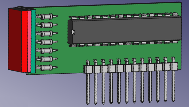
Figure 1 : Module
[ FreeCAD 0.20.1 ] , but follow your own ideas .

Figure 2 :
Module schematic . [EAGLE Version
6.4.0 für Windows Light Edition]
The complete AN can be downloaded as PDF : App-Note Driving a Single Digit LED Dot Matrix Display.pdf The source code, HEX file and XLS file can be downloaded as well : AN#209.zip
|