'File: X32E5 DDS Sinewave V1.bas
'Xmega32E5 DDS Program.
'Bascom
'Jay Carter
'April 2014, Revised Feb 2017
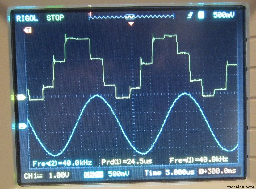
'This project is a simple DDS Sinewave generator for audio range signals.
'It outputs a Sine Wave on DAC output PortA.2
'It runs on an XmegaE5 micro that is running at 32 MHz, (i.e. not overclocked).
'It isn't optimized for speed, there is plenty of room for improvement.
'Arrays are Base 0, (Not the default Base 1).
'The Sinewave lookup table holds one full Period of the Sinewave.
'This ignores sinewave symmetry in order to keep it simple.
'Sinewave table has 256 entries, (0-255).
'Therefore can use 1 Byte as the Sinewave Index.
'Table pointer accumulator uses a Word type variable, scaling * 256.
'The upper byte is the Sine Lookup Table Index value!!!
'The full Word type is the DDS accumulator.
'The carry out of the Word is simply ignored.
'Xmega has a 12-Bit DAC, are only using 10 Bits at this time.
'There were several versions prior to this, so the comments may not always be
'up to date!
'This program uses < 10% of the Xmega32E5's memory.
'As structured, the DDS ISR is 62.5 KHz.
'There are 62,500 "Steps" in the output signal.
'For a clean output one MUST feed the signal through a Low Pass Filter.
'How "good" the waveform is, (Amount of Distortion), depends upon the
'output frequency.
'This program calculates the pointer to the next table value in the Main Loop.
'One could do this within the DDS ISR.
'In that case the program would be running mostly within the ISR, and the
'Main Loop could be NULL, or have user interface for setting frequency, etc.
'As long as the pointer to the next value is determined before the next DDS ISR
'interrupt comes along, it really doesn't matter which approach is used.
'Be careful if use Floating Point inside an ISR, it needs special register
'handling.
'This DDS has an update DAC rate of 62.5 KHz.
'During each Intr the new DAC value is loaded into the DAC, and a Flag is set.
'In Main the flag is recognized and the next DAC value is calculated.
'Calculated means determine the next sinewave sample to point to, and output
'on the next interrupt.
'The ISR Frequency determines how fast samples are outputted, and hence how many
'samples will be provided for the Sinewave.
'Output Sine 1 KHz 62.5 Samples / Period
'Output Sine 5 KHz 12.5 Samples / Period
'Output Sine 10 KHz 6.25 Samples / Period
'Note also that the DAC is running at 10 bits, not its full 12 bit resolution.
'Don't forget that with the XmegaE5 and the Timer/Counter C 4 Overflow ISR that
'one has to RESET the Overflow ISR Flag inside the ISR, manually!!!
'Note Well: Increasing the ISR rate ALSO decreases the time the forground has
'to process the data for the next DAC value. The calculation is interrupted
'more frequently, so it takes longer.!! Obvious, once one thinks about it.
'...............................................................................
'Hardware Setup and Notes:
'XMega runs at 2 MHz on startup, default.
'The XMega uses a PDI Programmer, 6-Pin Header is on the board.
'Use the Internal 32 MHz Osc.
'This PCB has a Nokia GLCD installed , which isn't used for this project.
'Hardware:
'Currently set up for my "Blue" Xmega32E5 PCB.
'Has a 4.00 MHz External Xtal installed.
'Available on Edge Connector Pads:
'PortA.1
'PortA.2 = DAC Output, (DAC0), Signal Output, unfiltered
'PortA.3 = DAC Output, (DAC1), Not being used.
'PortC.4 = LED2
'PortC.5 =
'PortC.6 =
'PortC.7 = LED3
'PortD.0 =
'Wired on PCB:
'PortA.4 = PB SW 3 Has External Pull-up resistors
'PortA.6 = PB SW 2 Has External Pull-up resistors
'PortA.7 = PB SW 1 Has External Pull-up resistors
'PortD.1 = LED1 Red LED adjacent the GLCD top right corner, High = On
'PortA.5 BT Module High Side Power Driver control, BT is not installed.
'PortD.4 = GLCD Data Clock, SCK
'PortD.5 = GLCD Data In, MOSI
'PortD.6 = GLCD D/C Mode
'PortD.7 = GLCD CS\
'PortC.0 = GLCD GLCD Backlight LED, High = On
'PortC.1 = GLCD Reset\
'PortR.0 External 4 MHz Xtal
'PortR.1 External 4 MHz Xtal
'-------------------------------------------------------------------------------
$regfile = "xm32E5def.dat" 'Micro in use
$crystal = 32000000 'Micro's Clock: 32 MHz
$hwstack = 192 'Hardware stack
$swstack = 192 'Software stack
$framesize = 192 'Frame space
Config Base = 0 'Arrays start with Index 0
Led1 Alias Portd.1 'Led1 Red High is On
Led2 Alias Portc.4 'Led2 Yellow High is On
Led3 Alias Portc.7 'LED3 Green High is On
' Scope Alias Portc_out.7 'O'Scope Probe
'Now Configure the Port's Pins for Input or Output mode.
'Config LEDs:
Portd_pin1ctrl = &B00000000 'PortD.1 Control Totem Pole Output
Portc_pin4ctrl = &B00000000 'PortC.4 Control Totem Pole Output
Portc_pin7ctrl = &B00000000 'PortC.7 Control Totem Pole Output
Portd_dir.1 = 1 'PortD.1 = Output
Portc_dir.4 = 1 'PortC.4 = Output
Portc_dir.7 = 1 'PortC.7 = Output
'Config PortA.2 for output for the DAC: (Not necessary)
' Porta_pin2ctrl = &B00000000 'PortA.2 Control Totem Pole Output
' Porta_dir.2 = 1 'PortA.2 = Output
'....................................................................................................
Dim J As Byte
Dim D As Byte
Dim Lpcnt As Word 'Loop Counter
Dim Ttcnt2 As Word 'Tick Toc ISR Counter
Dim Rvbit As Bit 'For Register Setup
Dim Regdata As Byte 'For Register Setup
Dim Lpcnt1 As Word 'Loop Counter
Dim Lpcnt2 As Word 'Loop Counter
Dim Isrcnt As Word 'ISR Counter TCD0, 1 intr q mSec
Dim Mainlp As Word 'Loop Counter, Main Loop
'Define several Values for the Xmega DAC
Dim Daccnt As Word 'DAC ISR Counter for rollover
Dim Dacch0val As Word 'Word Type Data to Feed DAC Ch0
Dim Dacch1val As Word 'Word Type Data to Feed DAC Ch1
'Dim DDS Direct Digital Synthesis Variables.
Dim Sintab(512) As Word 'Sin Lookup, Base 1
Dim Ddstmp As Single 'For Sin Table Calcs
Dim Ddsaccum As Single 'DDS Phase Accumulator
Dim Ddsgain As Single 'DDS DAC Gain Factor, <= 1.0
Dim Ddsindex As Word 'Index for SinTab()
Dim Fout As Single 'The desired Output Frequency, in Hz
Dim Dacflag As Byte 'ISR Set Flag for calculating next DAC value in Main
Dim Dacdata As Word 'Data Word for loading DAC with
Dim Dacdur As Word 'Counter for Duration of current tone
Dim Ddstmpw As Word 'Delta Phase * 100
Dim Ddsaccumw As Word 'DDS Phase Accum * 100
Dim Ddstmpdw As Dword 'Delta Phase * 1000, Dword type
Dim Ddsaccumdw As Dword 'DDS Phase Accum * 1000, Dword Type
Dim Tmpdw As Dword 'Calc variable
'Dim Arbitrary Waveform Gen Variables:
Dim Awfgindex As Word 'Sin Table Index BASE 0
Dim Awfgstep As Word 'Sample Table Incr Step Size
'///////////////////////////////////////////////////////////////////////////////
Startup:
'First set the Clock for 32 MHz via Internal RC Osc:
Gosub Clockopt1
'Briefly flash LEDs on start up, show that they work.
Set Led1
Waitms 250
Set Led2
Waitms 250
Set Led3
Waitms 250
Reset Led1
Reset Led2
Reset Led3
'...............................................................................
'Set up Timer/Counter C4 for DDS ISR:
'No hardware pins are controlled by this action.
'The Xmega Interrupt Controller must also be set up for this to function.
'My Xmega E5 Timer/Counter Setup for a desired Interrupt. System Clock = 32 MHz.
'NOTE WELL: One MUST manually Reset the Overflow Interrupt Flag inside the ISR.
'Otherwise it keeps retriggering, and ISR rate is very fast, and foreground crawls
'at one instruction per ISR firing.
'Given the uC's Clock, set the PreScaler divide by.
'Note, This PreScaler applies to ALL of the uC's Timer/Counters!
'Then set the Period for the desired interrupt rate.
'The T/C will roll over when it reaches TOP, or whatever the Period is set to.
'Be sure to reset the OVF Flag inside the ISR, or it will retrigger.
'Test Example:
'Intr at 1000 Hz for now, i.e. q 1 mSec
'Clock = 32 MHz.
'Prescaler is / 64. 32MHz/64 --> 500,000 Hz output of PreScaler.
'500K/500 = 1000.00 Hz as the OverFlow Intr Rate.
'Set TCC4_Per = 499 (Roll Over counts as 1)
'Example: Intr at 62500.0 Hz
'Clock = 32 MHz.
'Prescaler is / 64. 32MHz/64 --> 500,000 Hz output of PreScaler.
'500K/8 = 62500.0 Hz as the OverFlow Intr Rate.
'Set TCC4_Per = 7 for Div by 8, (Roll Over counts as 1)
'Example: Intr at 83333.333 Hz
'Clock = 32 MHz.
'Prescaler is / 64. 32MHz/64 --> 500,000 Hz output of PreScaler.
'500K/6 = 83333.333 Hz as the OverFlow Intr Rate.
'Set TCC4_Per = 5 for Div by 6, (Roll Over counts as 1)
'Example: Intr at 100,000 Hz
'Clock = 32 MHz.
'Prescaler is / 64. 32MHz/64 --> 500,000 Hz output of PreScaler.
'500K/5 = 100,000.0 Hz as the OverFlow Intr Rate.
'Set TCC4_Per = 4 for Div by 5, (Roll Over counts as 1)
'Setup for 62.5 KHz DDS ISR Interrupt Rate:
Config Tcc4 = Normal , Prescale = 64
Tcc4_per = 7 'TOP for TCC4 @ 62.5 KHz ISR
On Tcc4_ovf Ticktock2 , Saveall 'Define ISR Label
'Enable Tcc4_ovf , Hi 'Enable the Overflow ISR
'...............................................................................
'Set up Timer/Counter C5 as a heartbeat ISR.
'As the DAC ISR is High Priority, and this is Low Priority, it should be able
'to run with minimal jitter impact on the DAC output.
'Set this as LOW priority.
'Only one prescaler can be used for all of the T/C's on the E5.
'Prescaler is already set at /64 for TCC4.
'But still need it in the Instruction!
'The following example fires the ISR at 100.00 Hz.
'The ISR counts to 99, plus one for roll over, for a 1 Hz Led Flasher.
'Clock = 32 MHz.
'Prescaler is / 64. 32MHz/64 --> 500 kHz output of PreScaler.
'500 k / 5000 = 100.00 Hz as the OverFlow Intr Rate.
'Set TCC5_Per = 4999 to set Top to 5000. (Roll Over counts as 1)
Config Tcc5 = Normal , Prescale = 64
Tcc5_per = 4999 'Can change this once it works.
On Tcc5_ovf Heartbeat 'Define ISR Label
Enable Tcc5_ovf , Lo 'Enable the Overflow ISR
'....................................................................................................
Premain:
Gosub Initsintable 'Initialize DDS Sin Table
Gosub Dacsetup 'SetUp DAC Signal Output
Inits:
Ttcnt2 = 0 'Init ISR Counter
Lpcnt = 0 'Init Loop Counter
'Now Enable Global Interrupts and let the fun begin:
Config Priority = Static , Vector = Application , Hi = Enabled , Med = Enabled , Lo = Enabled
Enable Interrupts
'Init Variables:
Isrcnt = 0 'Init ISR Counter to 0
Dacch0val = 0 '4095 'Init Full Scale Mid -range
Dacch1val = 0 '4095 'Init Full Scale Mid-Range
Daccnt = 0 'Init ISR for DAC Counter
Awfgindex = 1 'Init Sin Table pointer
Awfgstep = 1 'Incr through each sample
Ddsaccum = 0 'Init Phase Accumulator
Dacflag = 0 'Init Flag to not set
Dacdur = 0 'Init Tone Duration Counter
Main:
'Generate a Fixed DDS Generated Output Signal:
'DDS ISR fires at 62.5 KHz and updates the DAC with the next value.
'Main Loop watches for flag from DDS ISR, then calculates the next
'DAC output value for when the ISR next fires.
'Prior to starting the loop:
'Pre-calculate the "Step size" for stepping through the Sin Table, based
'upon the output frequency, table size, and DAC update rate.
'*************
'Set the desired output frequency here, in Hz:
Fout = 1000 '1 kHz Output Freq
'*************
Ddsindex = 1 'Init DDS Table Index
Gosub Gensin 'Calc Delta Phase for this Output Frequency
Enable Tcc4_ovf , Hi 'Enable DAC ISR as High Interrupt
'Now let ISR update DAC value, and calculate next value in Main Loop.
'ISR sets a flag when it executes, so Main Loop knows when to calc the
'next value.
'Accumulator is a Word Type, and automatically rolls over at 65K.
'Its upper byte is the Sin Table Index.
Do
'Just watch for DDS ISR to set a flag, indicating that Main should
'calculate the next DAC output value for the ISR to use.
If Dacflag = 1 Then
'Need to Calc the next DAC value before next ISR comes along:
Ddsaccumw = Ddsaccumw + Ddstmpw 'Incr Phase Angle (* 256)
Ddsindex = High(ddsaccumw) 'Grab upper byte as SinTable Index
Dacdata = Sintab(ddsindex) 'Get the DAC Data Word
Dacflag = 0 'Reset the FLAG!
End If
Loop
End
'===============================================================================
'Xmega DACB Ch0 & Ch1 Testing, they feed an Audio Amp Chip.
Dacsetup:
'The XmegaE5 has one 12 Bit DAC, with two output channels.
'PortA.2 is DAC0 which this program uses.
'PortA.3 is DAC1 which is not in use.
'Bascom can set this up, direct Register setup is not required.
Config Daca = Enabled , Io0 = Enabled , Io1 = Enabled , Internal_output = Disabled , Channel = Dual , Trigger_ch0 = Disabled , Trigger_ch1 = Disabled , Reference = Avcc , Left_adjusted = Disabled , Event_channel = 0 , Interval = 64 , Refresh = 64
Return
Ticktock2:
'This is the DDS ISR.
'PortC Timer/Counter TCC4 ISR to update the DAC output value.
'The ISR Rate is set by the PortC Timer/Counter TCC$ setup.
'This routine outputs the next DAC value and sets a flag for the Main Loop.
'The Main Loop has to calculate the next value before the ISR fires again.
'On Entry have: DACData, Word, to load into the DAC.
'Could just use the Sin Table Index for this.
'On Exit have: Set DACFlag for Main to notice, and update DAC Calcs.
'Reset the Overflow Flag inside the ISR!
Tcc4_intflags = 1 'Clr Ovf Intr Flag
Daca0 = Dacdata 'Load DAC with Data Word
Dacflag = 1 'Set Flag, ISR Fired
Return
'+++++++++++++++++++++++++++++++++++++++++++++++++++++++++++++++++++++++++++++++
'DDS Routines:
'10 Bit DDS for now, (Xmega could do 12-Bit DDS).
'Ignore Sine wave symmetry for now.
'One full Period is stored in 256 entry lookup table:
Initsintable:
'Initialize a Sin Look-Up Table for 1 Period.
'Ignore Symmetry for now.
'N = 9, 2^N = 512 Entries in Table.
'Table has ADC/2 as DC Offset Set to 2047 as Midpoint.
'Sin going -1 to +1 full scale maps to 0 to 4095 or 4096...
'Table is indexed Base 1.
'Actual table goes: 2047 to 4093 to 2047 to 0 to 2047 over 1 period
'Storing Single into Word Type Table saves the Integer part of the
'single type calculation.
'Using a 512 byte array, 2^9 = 512
'360 Deg / 512 Samples --> 0.703125 Deg/sample
'*** Changed to 256 Entry Table, for 1 Byte Index into t=lookup table:
'2^n = 256, n = 8.
'360 / 256 = 1.40625 Degree / Sample
'Note: Changed to Base 0 for arrays with V4.
For Lpcnt1 = 0 To 255
Ddstmp = Lpcnt1 'Index for table 0-255
Ddstmp = Ddstmp * 1.40625 'Deg for this table entry, 0-360
Ddstmp = Deg2rad(ddstmp) 'Rads for this table entry, 0 - 2Pi
Ddstmp = Sin(ddstmp) 'Calc Sin for this table entry 0 to 0, range -1 to +1
'Now Multiply value, ranging -1 to +1, * 2047 so DAC value will range
'from -2047 to + 2047. Then add 2047 DC offset to center the DAC
'so the final DAC range is 0 - 2094 (missing the last value).
Ddstmp = Ddstmp * 2047 'Scale for Full Scale of DAC, (0-4095)
Ddstmp = Ddstmp + 2047 'Add DC offset to put sin midscale of DAC
Sintab(lpcnt1) = Ddstmp 'Store Table Entry
Next
Return
Gensin:
'Calculate the Delta Phase for this Output Frequency
'This calculates the step size for the lookup table for a given desired
'output frequency, number of table entries, and DAC update rate.
'On Entry have: Fout in Hz
'10-Bit Resolution used in Table, but note that Xmega has a 12-Bit DAC available.
'On Entry have: Fout The Output Freq in Hz. Single Type
'On Entry have: SinTab() Sine wave table, Base 0, 1 period's worth of samples.
'On Entry have: DDSGain The Gain Factor for the output, <= 1.0
'Calc the amount of Phase to Add to the Phase Accumulator for the given
'Input Freq, Lookup Table Size, and Output Clock (Sample Rate).
'For now assume Xmega is at 32 MHz clock,
'Sample Rate is 100 kHz, (Interrupt rate, Quite fast). <--- CHANGES with version
'Have about 320 Instr per Interrupt period for ISR and Main to Share!
'On Exit have: DDSTmp which is the Delta Phase, i.e. how many samples to
'skip over to get the next Sine Table sample to play for this Output Freq.
'On Exit have: DDSTmpW DDS Delta Phase as Word Type.
'
'Note: Instead of "rounding up" and back down in the calc loop, which is
'slow, multiple by 100 for two decimal places, or by 1000 to pick up three
'decimal places, but then ignore the rounding of the 4th decimal place.
'Note: CHANGED to 255 Entry Table for 1 byte lookup.
Ddsaccum = 0 'Init Phase Accumulator
Ddsaccumw = 0 'Init Phase Accum
Ddsaccumdw = 0 'Init Phase Accum
'Calc the Delta Phase to Add to the Phase Accumulator
'This gives the entry location in the Sin Table
'M = Step size through the table.
'2^n = Number of entries in 1 period of the sine wave, 1 period.
'512 entries gives n=9 65535 entries gives n=16, etc.
'N = the resolution of the phase accumulator.
'In the language: M = ((fout)(2^n))/Fref
'N=1024 , Fref = 100KHz, the DAC Sample output rate, Fout = output Freq in Hz
'Changed to new, lower ISR Rate of 38461.538 Intr / Sec
'Skip Gain for now, then add. It adds a lot of FP math.
'32MHz / 64 -> 500 kHz, 500 kHz / 5 = 100000 Samples / Sec (Div = 4+1)
'32MHz / 64 -> 500 kHz, 500 kHz / 6 = 83333.333 Samples / Sec (Div = 5+1)
'32MHz / 64 -> 500 kHz, 500 kHz / 13 = 38461.538 Samples / Sec (Div = 12+1)
'32MHz / 64 -> 500 kHz, 500 kHz / 17 = 29411.76 Samples / Sec (Div = 16+1)
'32MHz / 64 -> 500 kHz, 500 kHz / 10 = 50000 Samples / Sec (Div = 9+1)
'32MHz / 64 -> 500 kHz, 500 kHz / 8 = 62500 Samples / Sec (Div = 7+1)
Ddstmp = Fout * 256 'Single Type
'Select the DDS ISR Rate being used at the moment:
'Calculate the Delta Phase Shift per Interrupt:
Ddstmp = Ddstmp / 62500.0
'Now get the Delta Phase as a Word Type, (Scaled * 256)
Ddstmp = Ddstmp * 256.0 'Scale for Integer Math
Ddstmpw = Ddstmp 'Conv Single to Word Type * 256
Return 'Await next intr
Heartbeat:
'Timer/Counter TCC5 ISR for HeartBeat LED1.
'Fires at 100.00 Hz, q 10 mSec
'Low Priority
'Remember to RESET the ISR Flag inside the ISR on the E5's.
'Flash an LED for kicks:
Tcc5_intflags = 1 'Clr Ovf Intr Flag
Ttcnt2 = Ttcnt2 + 1 'Incr
If Ttcnt2 < 20 Then
Set Led1 'LED On
Else
Reset Led1 'Off
End If
If Ttcnt2 > 99 Then
Ttcnt2 = 0 'Rollover
End If
Return
Clockopt1:
'Set up the Xmega clock.
'Run on Internal 32 MHz Osc at 32 MHz
'Xmega runs at 2MHz on power up.
'Leave 2 MHz Osc enabled, and enable the Int 32MHz Clock
Config Osc = Enabled , 32mhzosc = Enabled
'Wait a bit to allow clocks to start up and stabilize.
'Note: Haven't yet switched to 32MHz, are at 2MHz, so Waitms 1 = 16 mSec
Waitms 4 'Wait 64mSec
'Next configure the systemclock:
Config Sysclock = 32mhz , Prescalea = 1 , Prescalebc = 1_1
Waitms 100 'Startup Stabilization Delay
Return
|